Photovoltaic Device

a photovoltaic device and photovoltaic technology, applied in the direction of heat collector mounting/support, solar heat collector safety, lighting and heating apparatus, etc., can solve the problems of large labor and material consumption, inconvenient mounting, and large labor needs and difficulties in working on the roo

Active Publication Date: 2014-03-27
BOE TECH GRP CO LTD +1
View PDF27 Cites 24 Cited by
  • Summary
  • Abstract
  • Description
  • Claims
  • Application Information

AI Technical Summary

Problems solved by technology

The above technique for the photovoltaic roof has disadvantages of: (1) complex structure, inconvenient mounting, great labor needs and difficulties in working on the roof; (2) large materials consumption, a large number of steps of materials processing and high labor costs; (3) non-durability, vulnerability, short life; (4) poor strength of connection between the roof and the battery assemblies and inconvenient maintenance and replacement; and (5) unfashionable and cumbersome appearance.
In addition, connections and junctions in the existing roof are filled and sealed with bricks, cement, felt, glue, or the like, thus resulting in inconvenience in construction, poo

Method used


Image

  • Photovoltaic Device
  • Photovoltaic Device
  • Photovoltaic Device

Examples


Embodiment Construction

[0046]One of the technical problems to be solved by an embodiment of the invention lies in improving the ability to resist wind load of a photovoltaic device while reducing difficulty in mounting the photovoltaic device.

[0047]In order to make objects, technical details and advantages of the embodiment of the invention apparent, the technical solutions of the embodiment will be described in a clearly and fully understandable way in connection with the drawings related to the embodiment of the invention. It is obvious that the described embodiment is just a part but not all of the embodiments of the invention. Based on the described embodiment herein, those skilled in the art can obtain other embodiment(s), without any inventive work, which should be within the scope of the invention.

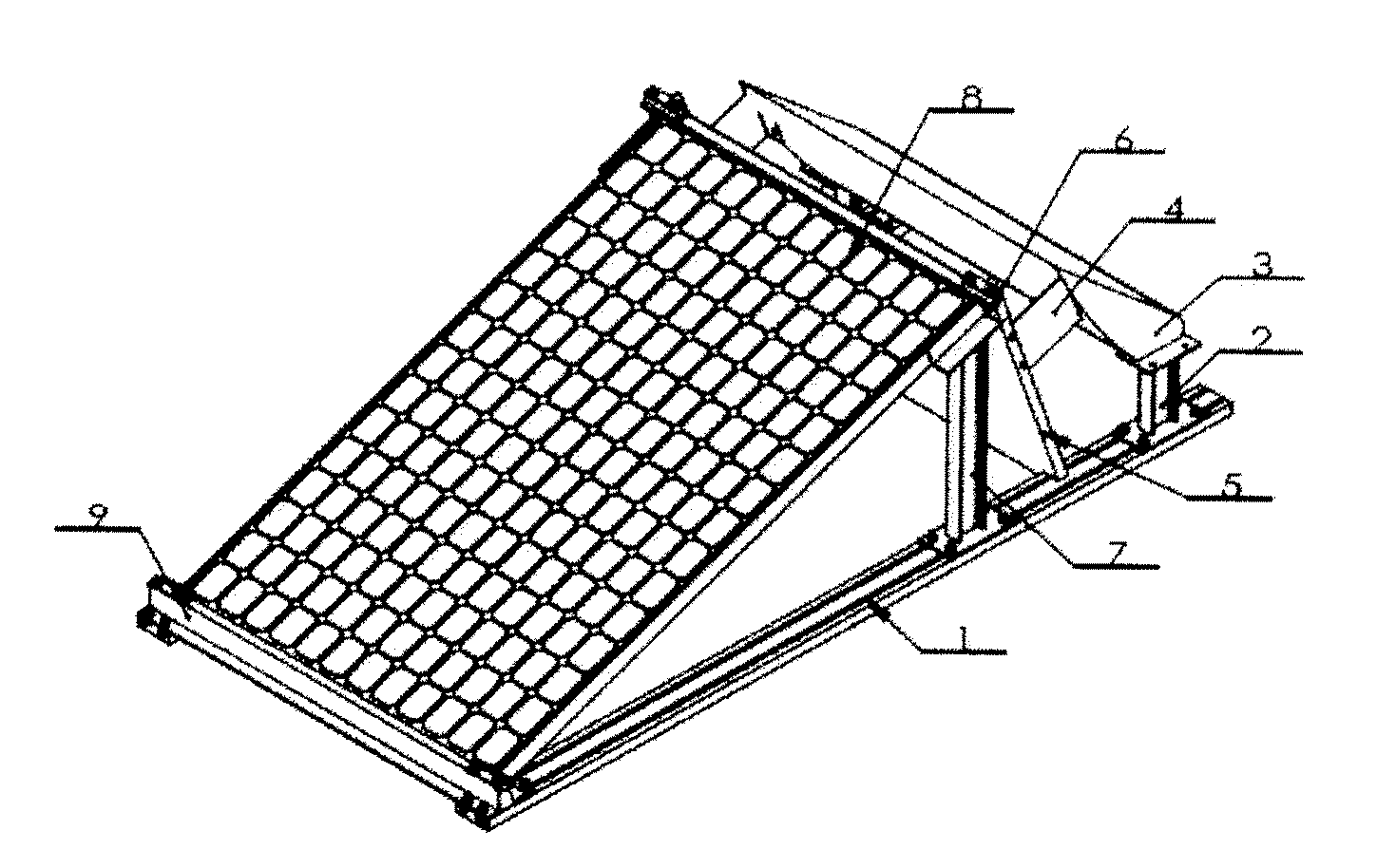
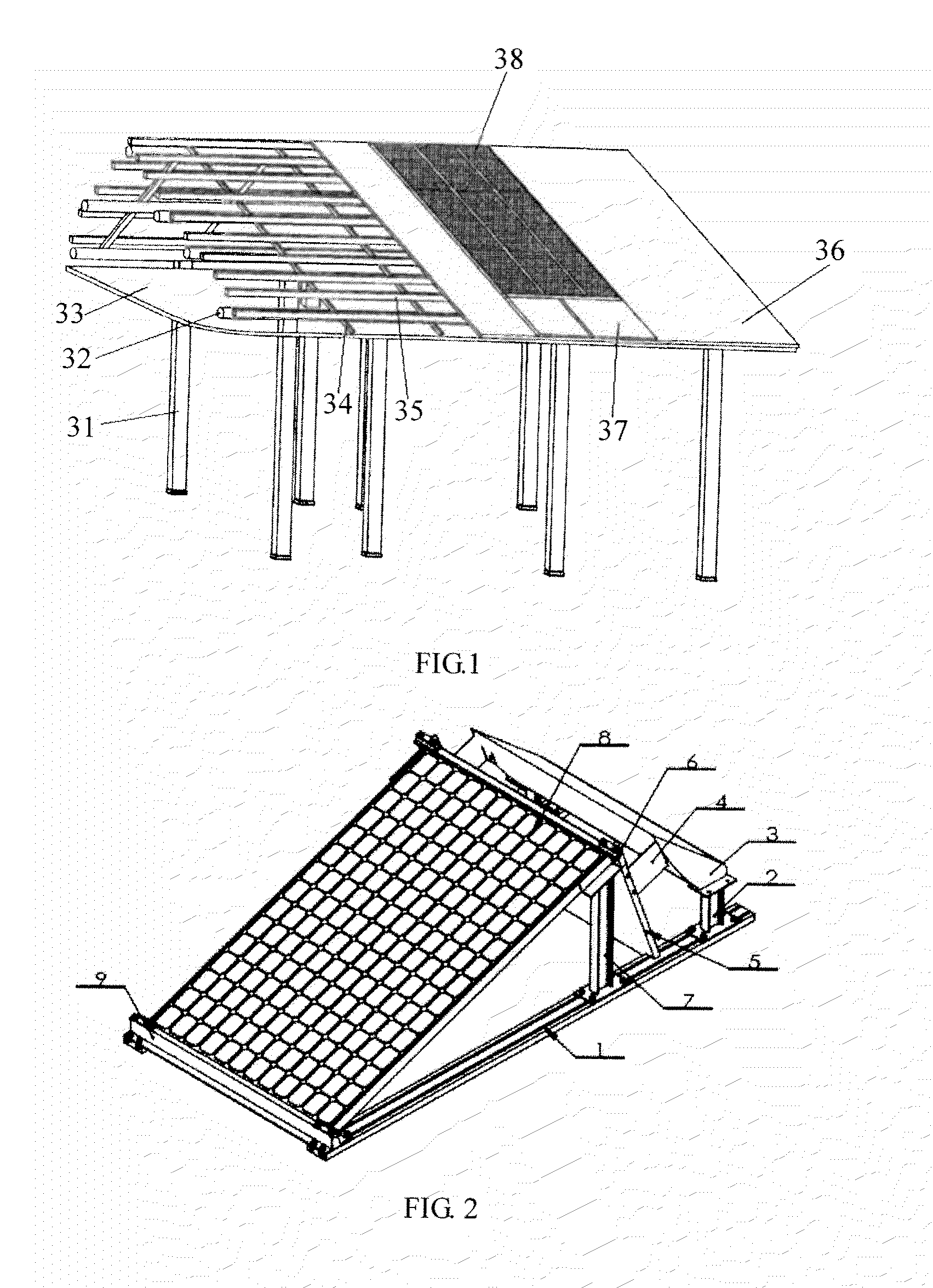
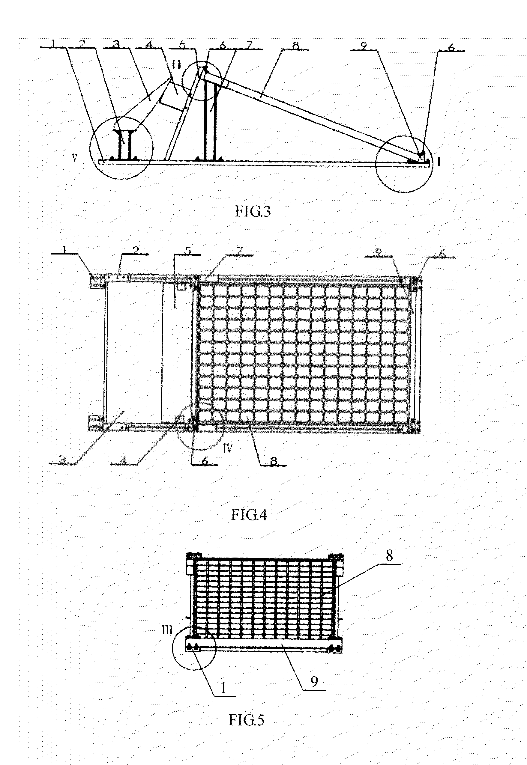
[0048]FIG. 2 shows a perspective view of a photovoltaic device of an embodiment of the invention; FIG. 3 is its side view; FIG. 4 is its top view; and FIG. 5 is its front view. As shown in these figures, ...


PUM


Abstract

A photovoltaic device comprising: a base (1), a photovoltaic assembly (8) and a baffle plate (5), wherein the photovoltaic assembly is arranged in an inclined manner on the base from bottom up in a direction from front to rear, and behind the photovoltaic assembly, the baffle plate is arranged in an inclined manner on the base from bottom up in a direction from rear to front. The baffle plate reduces the profile coefficient and decreases the uplift by the action of wind load.

Description

TECHNICAL FIELD[0001]Embodiments of the present invention relate to a photovoltaic device.BACKGROUND[0002]Building energy conservation and photovoltaic power generation are important development trends of modern construction industry. Accordingly, a building integrating photovoltaic is a new technique of great potential and significant value. A photovoltaic device for the roof of a building mainly comprises battery assemblies constructed by solar cells and carriers, and the battery assemblies are mounted on the part of the roof facing the sun. In the solar battery assemblies, light energy is converted into electrical energy which is gathered and input to an electrical grid. There are numbers of relatively mature technical solutions for gathering and inputting electrical energy to an electrical grid. The photovoltaic device generally has a structure, as shown in FIG. 1, comprising: pillars 31, beams 32 with dividing strip 34 and grilles 35 mounted thereon, and a ceiling 33; a house p...

Claims


Application Information

Patent Timeline
IPC IPC(8): H01L31/042H02S20/10H02S30/00
CPCY02E10/50F24J2/5233H01L31/0484Y02E10/47H01L31/0422Y02B10/12H02S20/00H02S20/24F24S40/53F24S40/85F24S25/30F24S25/13F24S2025/02Y02B10/10H01L31/042
Inventor SONG, HANGBINYANG, PEIHUAN
Owner BOE TECH GRP CO LTD
Why Eureka
Try Eureka