Light source device

a light source and light source technology, applied in the direction of lamp incadescent bodies, gas filling substances, electrical apparatus, etc., can solve the problems of low conversion efficiency of electric power to visible light, affecting the efficiency of electrical power-to-visible light conversion, and imposing large environmental loads, so as to reduce electron scattering, reduce energy consumption, and reduce the effect of strength and ductility

Active Publication Date: 2014-03-27
STANLEY ELECTRIC CO LTD
View PDF1 Cites 0 Cited by
  • Summary
  • Abstract
  • Description
  • Claims
  • Application Information

AI Technical Summary

Benefits of technology

[0011]According to the present invention, a single crystal filament containing no grain boundary or almost no grain boundary is used, and therefore it is hardly deformed, and shows high strength, even when it is heated to a high temperature. Further, since it does not contain lattice defects such as grain boundary, it can reduce electron scattering, thereby improve reflectance (reduce emissivity) for the long wavelength region, and increase radiation efficiency for the visible region.

Problems solved by technology

However, although incandescent light bulbs show high electric power-to-light conversion efficiency (80% or higher), much of the light thereby produced consists of infrared radiation components as shown in FIG. 6 (90% or more in the case of 3000K shown in FIG. 6), and therefore the electric power-to-visible light conversion efficiency thereof is low.
In addition, although incandescent light bulbs show a radiation spectrum close to sunlight providing superior color rendering properties, they have a problem that they impose large environmental loads.
Moreover, it is well known that if grain size of metallic materials including tungsten becomes large due to recrystallization, strength and ductility thereof decrease.
Therefore, if a filament coil made of pure tungsten is used at a high temperature, slippage occurs at crystal grain boundaries extending along the radial direction of the filament, and the filament is easily deformed with a small external force such as own weight (creep deformation).
Therefore, the filament comes to be easily locally heated, and easily cause disconnection.

Method used


Image

  • Light source device
  • Light source device
  • Light source device

Examples


Embodiment Construction

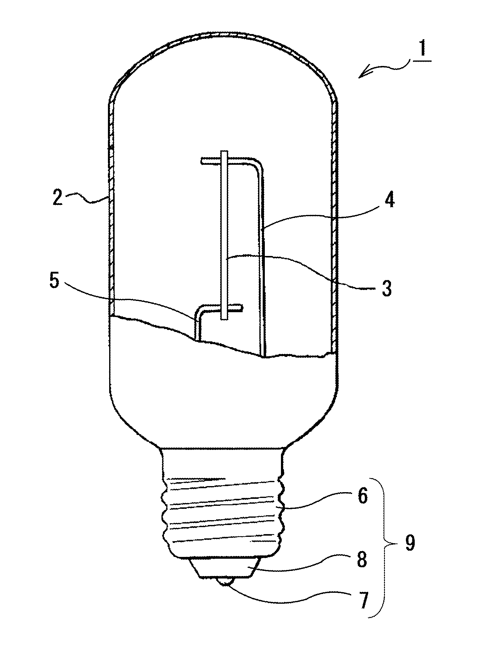
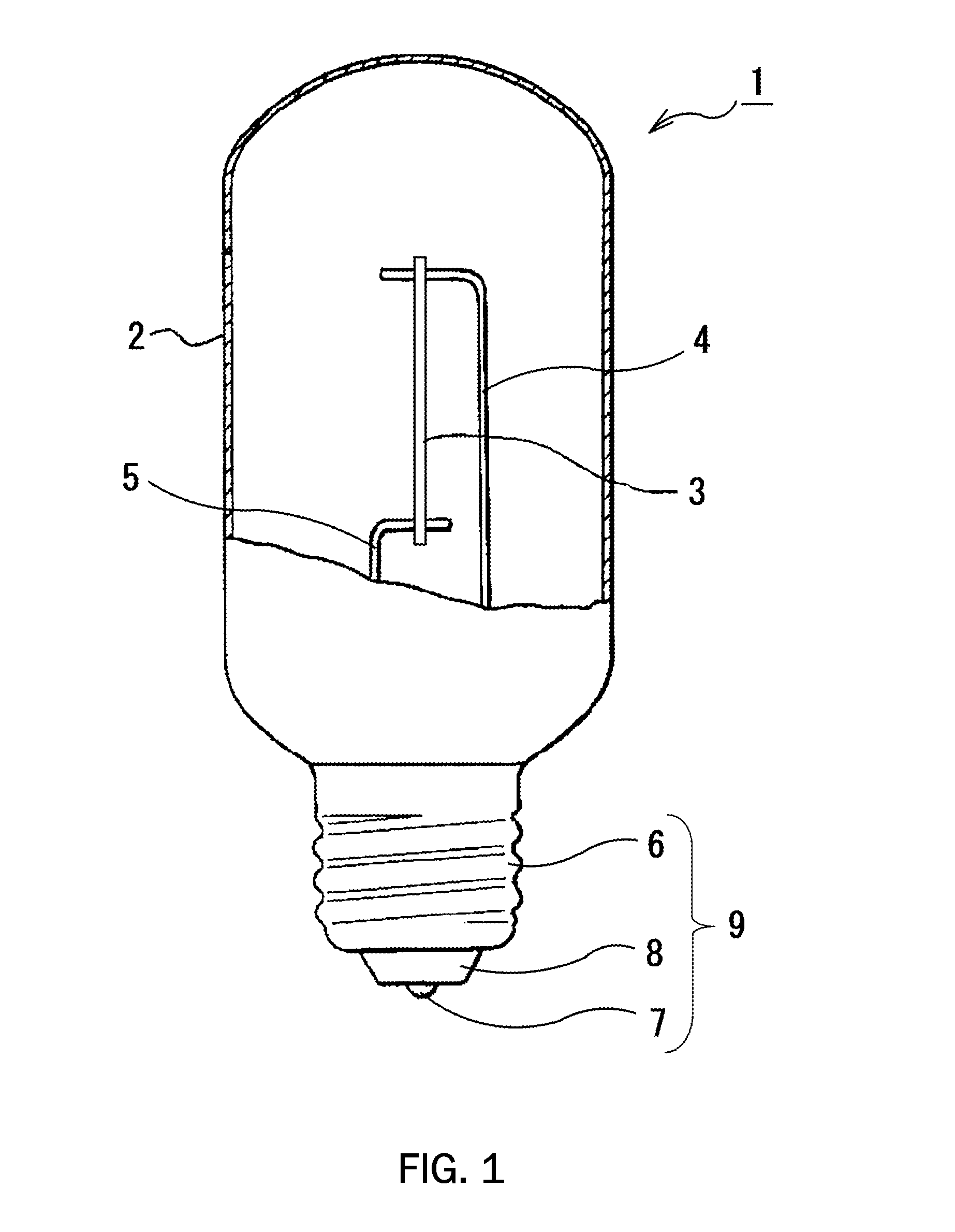
[0018]In the present invention, a single crystal is used for a filament of a light source device. Since a single crystal filament contains no grain boundary or almost no grain boundary unlike a polycrystal filament, it does not cause slippage at crystal boundaries like a polycrystal filament. Therefore, it does not cause creep deformation due to an external force such as own weight even when it is heated to a high temperature, and it does not easily cause local temperature elevation and disconnection.

[0019]Although the single crystal filament referred to in the present invention preferably contains no grain boundary, it may contain grain boundaries at such a low level that it can be considered to contain substantially no grain boundary compared with a polycrystal. For example, it may contain several grain boundaries. However, even when the single crystal filament contains a few grain boundaries, it is desirable that axial orientations of the crystals divided by these grain boundarie...


PUM


Abstract

A filament of simple structure showing improved conversion efficiency is provided. There is provided a light source device comprising a light-transmitting gas-tight container, a filament disposed in the light-transmitting gas-tight container, and a lead wire for supplying an electric current to the filament, wherein the filament consists of a single crystal. Sum of concentration of lattice defects and impurity concentration of the filament consisting of a single crystal is preferably lower than 0.01%.

Description

TECHNICAL FIELD[0001]The present invention relates to a light source device utilizing a filament showing high visible light conversion efficiency.BACKGROUND ART[0002]There are widely used incandescent light bulbs which produce light with a filament such as tungsten filament heated by an electric current flown through it. However, although incandescent light bulbs show high electric power-to-light conversion efficiency (80% or higher), much of the light thereby produced consists of infrared radiation components as shown in FIG. 6 (90% or more in the case of 3000K shown in FIG. 6), and therefore the electric power-to-visible light conversion efficiency thereof is low. Specifically, visible light conversion efficiency of incandescent light bulbs is as low as about 15 lm / W (visible light conversion efficiency of fluorescent lamps is 90 lm / W). In addition, although incandescent light bulbs show a radiation spectrum close to sunlight providing superior color rendering properties, they hav...

Claims


Application Information

Patent Timeline
Patent Type & Authority Applications(United States)
IPC IPC(8): H01K1/04
CPCH01K1/04H01K1/08H01K1/10H01K3/02
Inventor MATSUMOTO, TAKAHIRO
Owner STANLEY ELECTRIC CO LTD
Why Eureka
Try Eureka