
Methods and systems for controlling bubble size and bubble decay rate in foamed glass produced by a submerged combustion melter

a combustion melter and foamed glass technology, which is applied in the field of combustion furnaces and methods of use to produce glass, can solve the problems of reducing the foam rate through scm process adjustments, rapid melting of glass batches, and high turbulence, and achieves the effects of reducing the foam rate, reducing the turbulence, and reducing the turbulen

Active Publication Date: 2014-04-03
JOHNS MANVILLE CORP
View PDF6 Cites 41 Cited by
  • Summary
  • Abstract
  • Description
  • Claims
  • Application Information

AI Technical Summary

Benefits of technology

The patent text describes methods for controlling the size and lifespan of bubbles in glass foam. One method involves using an oxygenated sulfur compound and optionally oxygen to stabilize the bubble size and decay rate. Another method involves dropping a mixture of alkali metal chalcogen particles and glass particles onto the foam to increase its decay rate. Additionally, the text mentions increases in foam decay rate by either fully saturating the gaseous atmosphere with water vapor or injecting steam into the atmosphere. Overall, the patent provides technical means for controlling bubble size and lifespan in glass foam.

Problems solved by technology

The introduction of high flow rates of products of combustion of the oxidant and fuel into the molten glass, and the expansion of the gases cause rapid melting of the glass batch and much turbulence, and possibly foaming.
With regard to SCMs, attempts to reduce the foam through SCM process adjustments, such as use of helium and steam to scavenge and consolidate bubbles, sonic methods to consolidate bubbles, vacuum to increase bubble size, and centrifugal force have not met with complete success in reducing foam from an SCM to an acceptable amount.

Method used


Image

  • Methods and systems for controlling bubble size and bubble decay rate in foamed glass produced by a submerged combustion melter
  • Methods and systems for controlling bubble size and bubble decay rate in foamed glass produced by a submerged combustion melter
  • Methods and systems for controlling bubble size and bubble decay rate in foamed glass produced by a submerged combustion melter

Examples


examples

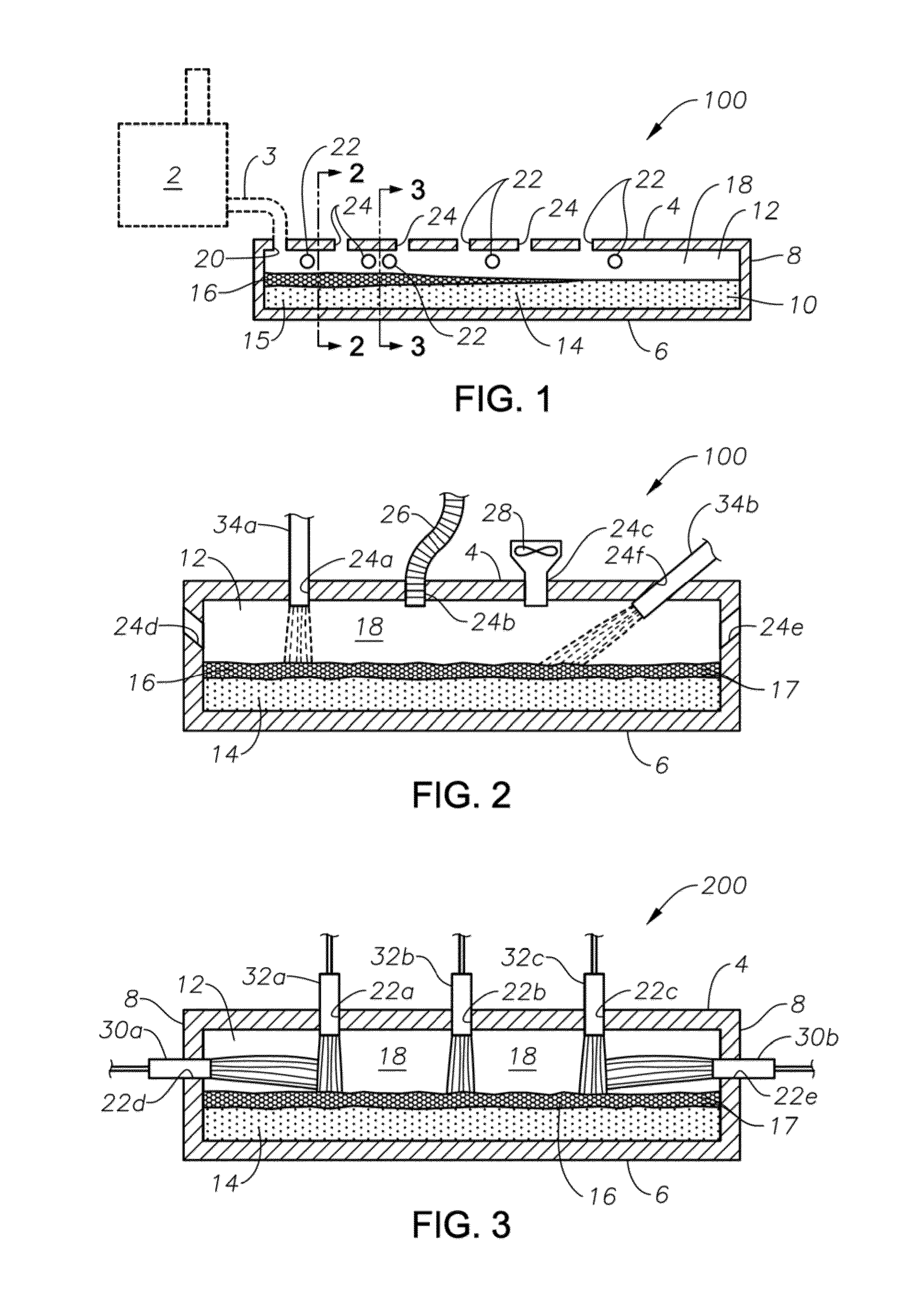
[0094]Laboratory testing was carried out to evaluate use of atmospheres of different compositions to influence the foam decay rate and the size of the bubbles within the glass foam layer of glass compositions produced from an SCM. Nine trial conditions were tested, the details of which are detailed herein. Videos were made of all trials and bubble size measurements were made of the noted trials.

[0095]The experiments were conducted by placing 20 grams of SCM melter discharge (E-glass) into a quartz tube and placing the tube into a pre-heated furnace at 1375° C. The atmosphere inside of the tube, considered to be a reasonable simulation of the conditions inside the atmosphere of an apparatus downstream of an SCM, was controlled by adding gases of specific mixture from a gas mixing and flow control station to the top of the tube. The tube was sealed with a high temperature refractory fiber so that the ambient air was sealed outside the tube and only the gases from the mixing and flow c...


PUM


Abstract

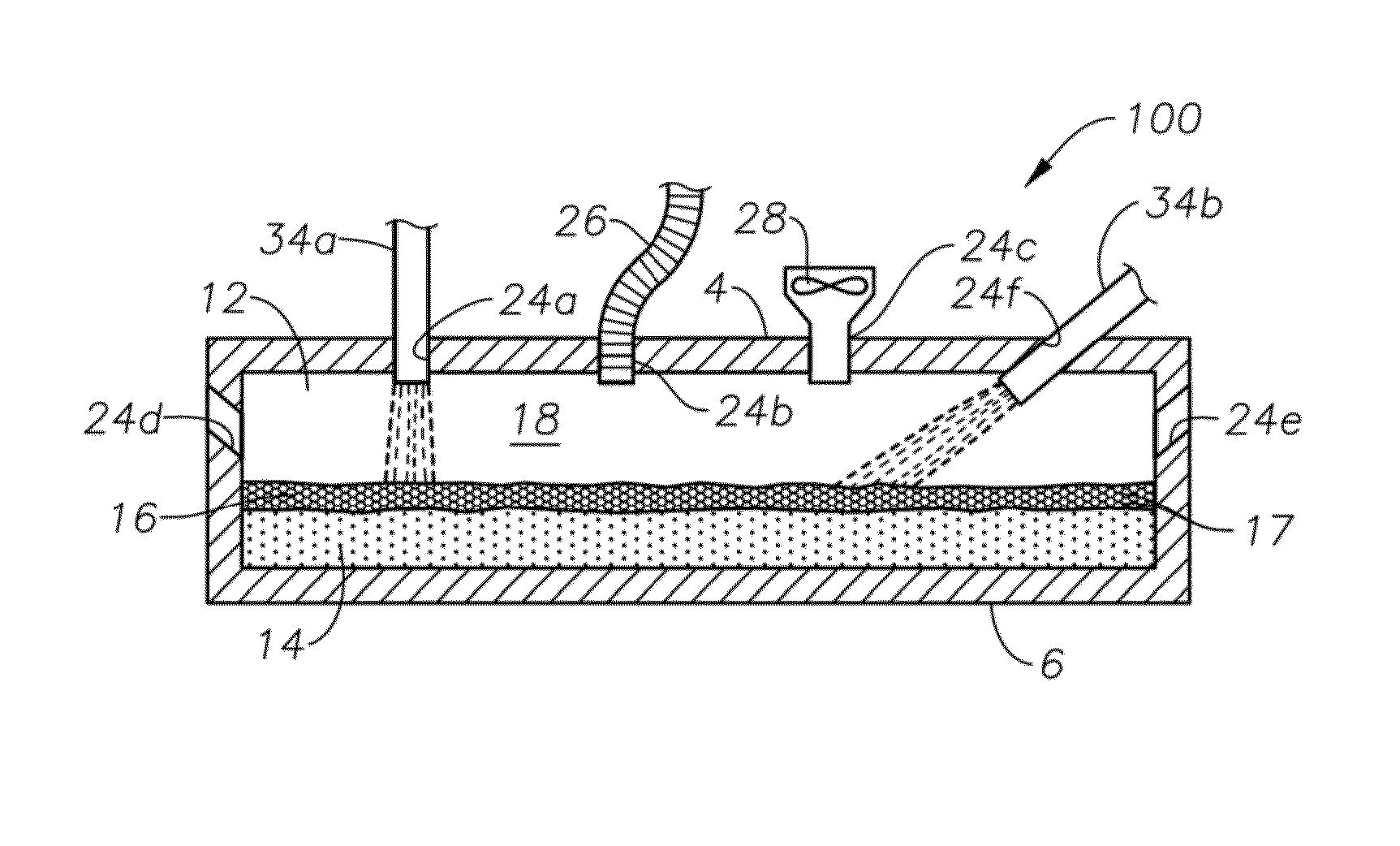
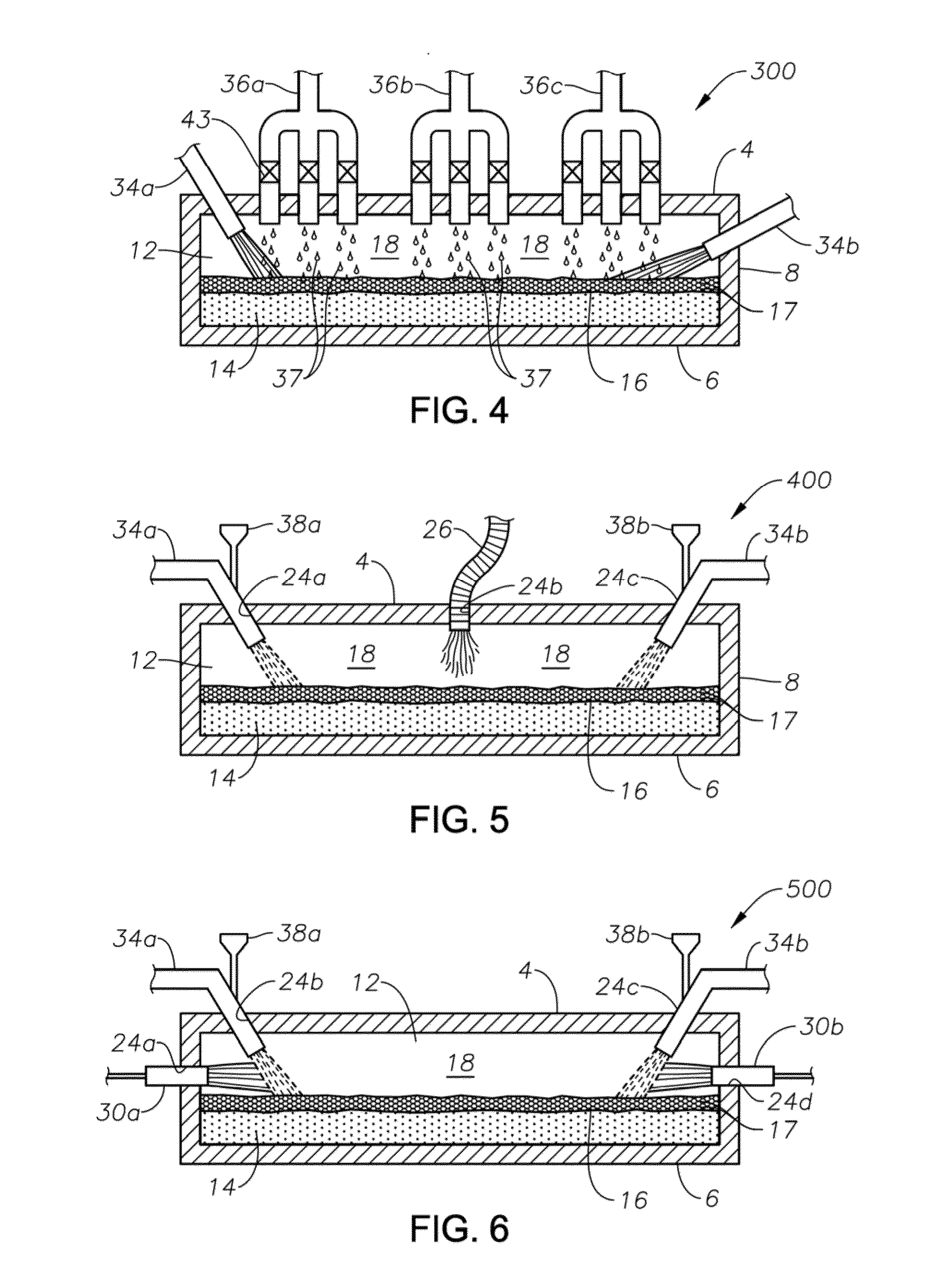
Methods and systems for controlling bubble size and bubble decay rate of glass foams formed during submerged combustion melting. Flowing a molten mass of foamed glass comprising molten glass and bubbles entrained therein into an apparatus downstream of a submerged combustion melter. The downstream apparatus has a floor, a roof, and a sidewall structure connecting the floor and roof. The foamed glass has glass foam of glass foam bubbles on its top surface, and the downstream apparatus defines a space for a gaseous atmosphere above and in contact with the glass foam. The downstream apparatus includes heating components to heat or maintain temperature of the foamed glass. Adjusting composition of the atmosphere above the glass foam, and / or contacting the foam with a liquid or solid composition controls bubble size of the glass foam bubbles, and / or foam decay rate.

Description

CROSS-REFERENCE TO RELATED APPLICATIONS[0001]This application may be related to the following United States non-provisional patent applications assigned to the assignee of the present application which are all incorporated by reference herein: U.S. Ser. No. 12 / 817,754, filed Jun. 17, 2010; U.S. Ser. Nos. 13 / 267,990, 13 / 268,028, 13 / 268,098, and 13 / 268,130, all four filed Oct. 7, 2011; U.S. Ser. No. 13 / 458,211, filed Apr. 27, 2012; U.S. Ser. Nos. 13 / 493,170 and 13 / 493,219, both filed Jun. 11, 2012; U.S. Ser. No. 13 / 540,771, filed Jul. 3, 2012. U.S. patent applications identified as Attorney Docket Nos. 8144-1, 8144-2, 8147 and 8154 are being filed on even date herewith.BACKGROUND INFORMATION[0002]1. Technical Field[0003]The present disclosure relates generally to the field of combustion furnaces and methods of use to produce glass, and more specifically to methods and systems to control bubble size and / or foam decay rate in glass handling equipment downstream of a submerged combustion...

Claims


Application Information

Patent Timeline
IPC IPC(8): C03B5/193
CPCC03B5/193C03B5/202C03B5/225C03B5/235C03B5/2353C03B5/2356Y02P40/50C03B2211/40
Inventor SHOCK, JEFFREY MCHARBONNEAU, MARK WILLIAM
Owner JOHNS MANVILLE CORP
Learn More