Metal foil pattern layered body, metal foil layered body, metal foil multi-layer substrate, solar cell module, and method of manufacturing metal foil pattern layered body

Active Publication Date: 2014-04-03
ENDURANCE SOLAR SOLUTIONS BV
View PDF6 Cites 8 Cited by
  • Summary
  • Abstract
  • Description
  • Claims
  • Application Information

AI Technical Summary

Benefits of technology

The invention prevents the removal of a metal foil pattern by using burrs that have an anchor effect on the adhesive layer, improving durability. It also avoids damage to the top surface of the base member, maintaining high reliability levels. The invention includes an insulating layer that is attached firmly to the metal foil, preventing it from being removed or displaced. The edge face of the metal foil is inclined with a protuberance protruding to the insulating layer. This results in a vertical connection between the metal foil and the insulating layer, ensuring the pattern's configuration is integrally formed.

Problems solved by technology

In contrast, in this technique, patterning of the resist material is necessary, there is a problem in that the patterning of the resist material is difficult in accordance with a large-scaled metal foil.
Additionally, since a large amount of etching solution for chemically milling a metal foil is used, installation of a facility required for processing the etching solution and a large amount of cost required for environmental measures or the like are necessary.
Consequently, when the solar cells 630 adjacent to each other are connected through the wiring members 650, the wiring members 650 overlap the light-receiving face 630a of the solar cell 630, and there is a drawback in that the area efficiency of photoelectric conversion is degraded.
However, in the case of die-cutting the metal foil which is stacked on the base member with the adhesive layer interposed therebetween, it is necessary remove an unnecessary region, that is an unnecessary portion of the metal foil, from the adhesive layer after the die-cutting.
However, when the winding up is carried out, there is a concern that not only the unnecessary region of the metal foil but also a necessary region that is to be left as a metal foil pattern is removed.
In addition, when die-cutting is performed using a blade die, a cutting depth of the blade is suitably set; however, if the cutting edge of the blade does not reach the back face of the metal foil, it is not possible to reliably cut the metal foil.
On the other hand, if a cutting depth of the blade is excessively large, the cutting edge of the blade damages to the top face of the base member, product reliability is degraded.
However, the thickness of the adhesive layer is thin such as approximately 10 μm, it is difficult to adjust the cutting depth.
Additionally, regarding the metal foil pattern layered bodies shown in FIGS. 28 and 29, in the case of forming a circuit pattern on the metal foil by etching, a large amount of chemical solutions or materials such as resists such as photoresists or the like, etching solution, remover for remaining resists, or the like is necessary, it is complicated, and the cost of manufacturing is high.
Furthermore, there is a defect that a metal foil or the like may be damaged due to use of chemical solutions such as etching solution, resist remover, or the like.
Moreover, in the case where a circuit pattern is manufactured by not only etching but also punching a metal foil with a punching blade, an edge face of the circuit pattern of the metal foil is formed vertical to the base member and, and there is a concern that the insulating layer is removed from the metal foil of circuit pattern when stacking an insulating layer on the circuit pattern.
Therefore, the metal foil pattern layered body may be defective.
Consequently, since the edge face of the circuit pattern of the metal foil is vertically formed, the seal member sealing the solar cells may be removed from the metal foil of the circuit pattern, and displacement of the seal member with respect to the metal foil of the circuit pattern may occur; contact failure between the electrode of the solar cell and the electrode of the circuit pattern, which is due to misalignment, may occur.
Additionally, regarding the metal foil layered bodies having the wiring pattern shown in FIGS. 28 and 30, in the case of forming a wiring pattern on the metal foil by etching, a large amount of chemical solutions or materials such as resists, etching solution, remover for remaining resists, or the like is necessary, it is complicated, and the cost of manufacturing is high.

Method used


Image

  • Metal foil pattern layered body, metal foil layered body, metal foil multi-layer substrate, solar cell module, and method of manufacturing metal foil pattern layered body
  • Metal foil pattern layered body, metal foil layered body, metal foil multi-layer substrate, solar cell module, and method of manufacturing metal foil pattern layered body
  • Metal foil pattern layered body, metal foil layered body, metal foil multi-layer substrate, solar cell module, and method of manufacturing metal foil pattern layered body

Examples


first embodiment

[0195]Firstly, a solar cell module 100 including a metal foil pattern layered body 10 of a first embodiment of the invention will be particularly described with reference to FIGS. 1 to 6.

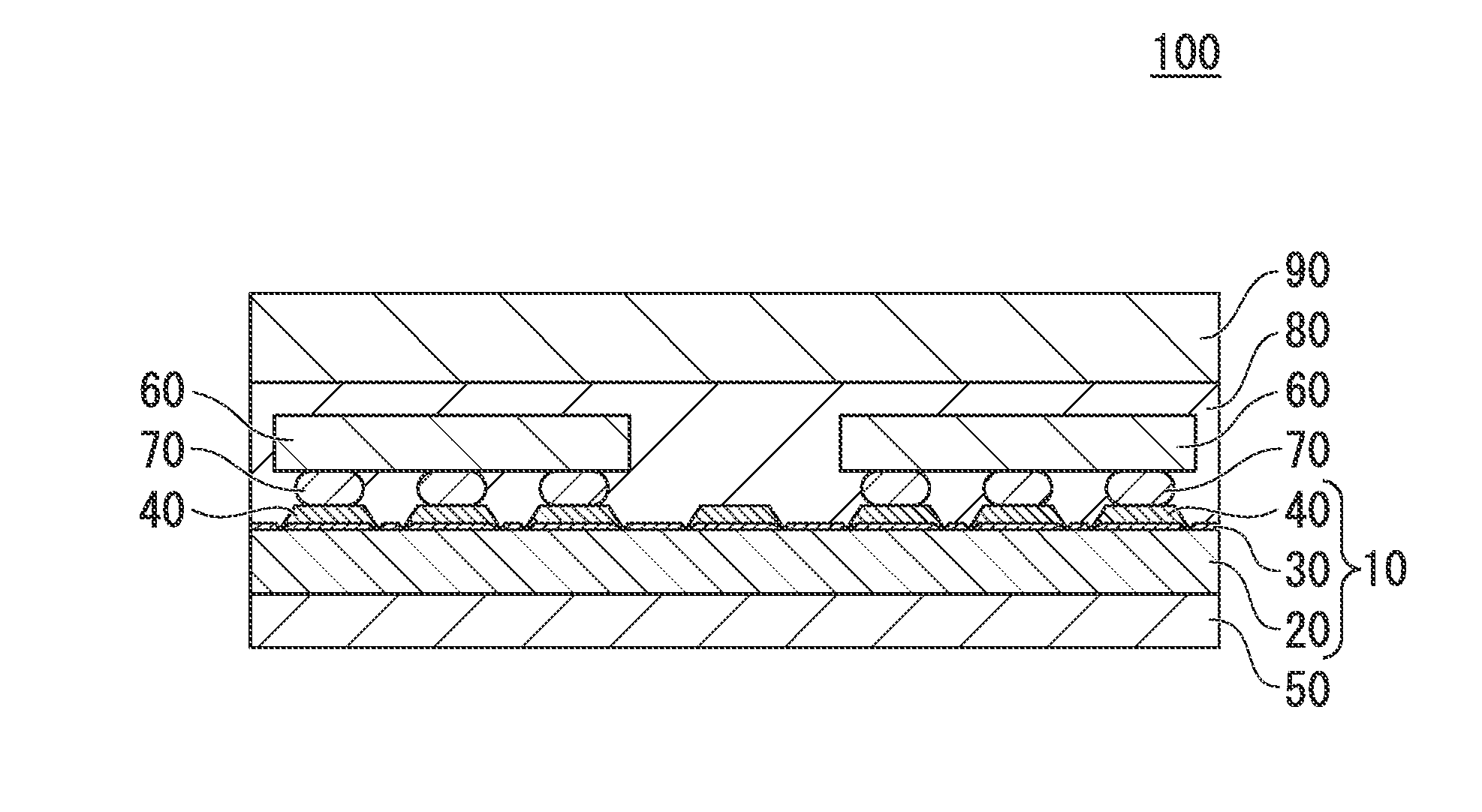
[0196]FIG. 1 is a vertical cross-sectional view showing the solar cell module 100 of the first embodiment.

[0197]The solar cell module 100 is provided with: a metal foil pattern layered body 10; a back sheet 50 that is provided at the back face side of the metal foil pattern layered body 10 (lower side of the metal foil pattern layered body 10 in FIG. 1, and the position close to the back face of the metal foil pattern layered body 10); a plurality of solar cells 60 that are provided at the top face side of the metal foil pattern layered body 10 (upper side of the metal foil pattern layered body 10 in FIG. 1, and the position close to the top face of the metal foil pattern layered body 10); a seal member 80 that seals the solar cells 60 on the metal foil pattern layered body 10; and a light-transmiss...

second embodiment

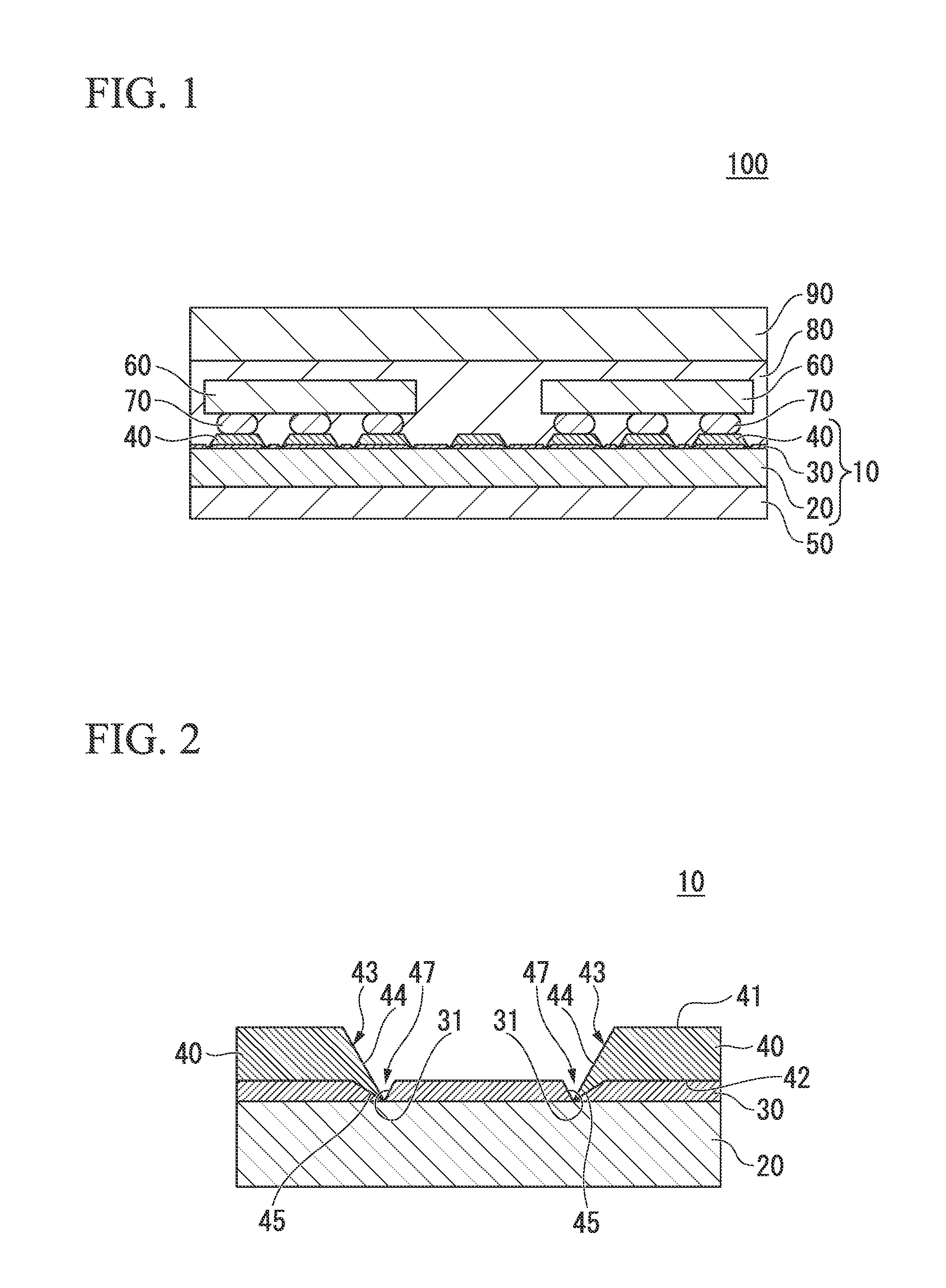
[0295]Next, a metal foil pattern layered body 15 of a second embodiment of the invention will be explained with reference to FIG. 7.

[0296]In FIG. 7, identical symbols are used for the elements which are identical to those of FIG. 2, and detailed explanations thereof are omitted here.

[0297]The configuration of the cut portion 47 of the metal foil pattern layered body 15 of the second embodiment is different from that of the first embodiment.

[0298]The cut portion 47 of the second embodiment is continuously formed inside the adhesive layer 30 and inside the base member 20.

[0299]That is, the cut portion 47 is defined by a first base member inclined surface 21a, the adhesive-layer inclined surface 31, and a second base member inclined surface 21b.

[0300]Here, the first base member inclined surface 21a forms a continuous surface with the first inclined surface 44 and is formed inside the base member 20 so as to extend along the first inclined surface 44.

[0301]The second base member inclin...

third embodiment

[0310]Next, a solar cell module 100 provided with a metal foil pattern layered body 210 of a third embodiment of the invention will be particularly described with reference to FIGS. 8 to 12.

[0311]In the third embodiment, identical symbols are used for the elements which are identical to those of the first embodiment and the second embodiment, and the explanations thereof are omitted or simplified here.

[0312]FIG. 8 is a vertical cross-sectional view showing the solar cell module 200 of the third embodiment.

[0313]The solar cell module 200 is provided with: a metal foil pattern layered body 210; a back sheet 50 that is provided at the back face side of the metal foil pattern layered body 210 (lower side of the metal foil pattern layered body 210 in FIG. 8, and the position close to the back face of the metal foil pattern layered body 210); a plurality of solar cells 60 that are provided at the top face side of the metal foil pattern layered body 210 (upper side of the metal foil patter...


PUM

PropertyMeasurementUnit
Timeaaaaaaaaaa
Angleaaaaaaaaaa
Angleaaaaaaaaaa

Abstract

A metal foil pattern layered body of the invention includes: a base member; a metal foil including a metal foil pattern formed by an opening and a metal portion; and a protuberance provided at the metal foil and at a boundary between the opening and the metal portion.

Description

CROSS REFERENCE TO RELATED APPLICATIONS[0001]This application is a continuation application based on a PCT Patent Application No. PCT / JP2012 / 064594, filed Jun. 6, 2012, whose priority is claimed on Japanese Patent Application No. 2011-126516 filed on Jun. 6, 2011, Japanese Patent Application No. 2011-126517 filed on Jun. 6, 2011, Japanese Patent Application No. 2011-126518 filed on Jun. 6, 2011, and Japanese Patent Application No. 2011-126520 filed on Jun. 6, 2011, the contents of which are hereby incorporated by reference in their entirety.BACKGROUND OF THE INVENTION[0002]1. Field of the Invention[0003]The present invention relates to a metal foil pattern layered body, a metal foil layered body, a metal foil multi-layer substrate, solar a cell module, and a method of manufacturing a metal foil pattern layered body.[0004]Particularly, the present invention relates to a metal foil pattern layered body used to electrically connect so-called back contact solar cells to each other, and ...

Claims


Application Information

Patent Timeline
IPC IPC(8): H05K1/02H01L31/05H05K3/20
CPCH05K3/041H05K3/284H05K2201/0195Y02E10/50H01L31/0516H05K3/20H05K2203/0108H05K1/02H05K3/3431H05K2201/10143Y10T29/301H01L31/042
Inventor KUMAI, KOICHIUEDA, RYUJITOMONO, TAKAOTSUKAMOTO, TAKEHITO
Owner ENDURANCE SOLAR SOLUTIONS BV
Why Eureka
Try Eureka