Systems and methods for operating symbology reader with multi-core processor

a symbology reader and multi-core processor technology, applied in the field of machine vision systems, can solve the problems of inapplicability to inability to apply solutions for certain object geometries and line arrangements, and the cost of line scan (i.e. one-dimensional) image sensors is more expensive than conventional rectangular format sensors, so as to achieve effective dissipation of internal generated heat, move relatively quickly, and achieve high efficiency

Active Publication Date: 2014-04-10
COGNEX CORP
View PDF0 Cites 67 Cited by
  • Summary
  • Abstract
  • Description
  • Claims
  • Application Information

AI Technical Summary

Benefits of technology

[0008]This invention overcomes disadvantages of the prior art by providing a vision system camera, and associated methods of operation, having a multi-core processor, high-speed, high-resolution imager, field of view expander (FOVE), auto-focus lens and imager-connected pre-processor to pre-process image data provides the acquisition and processing speed, as well as the image resolution that are highly desirable in a wide range of applications. This arrangement is highly effective in scanning objects that require a wide field of view, vary in size and the positioning of features of interest and move relatively quickly with respect to the system field of view. This vision system provides a physical package with a wide variety of physical interconnections to support various options and control functions. The package effectively dissipates internally generated heat by arranging components so as to optimize heat transfer to the ambient environment and includes dissipating structure (e.g. fins) to facilitate such transfer. The system also enables a wide range of multi-core processes to optimize and load-balance both image processing and system operation (i.e. auto-regulation tasks).
[0009]In an illustrative embodiment a vision system includes a camera housing enclosing an imager and processor arrangement. The processor arrangement includes (a) a pre-processor interconnected to the imager that receives, at a first frame rate (e.g. 200 to more than 300 images per second), and pre-processes images from the imager, and (b) a multi-core processor (with a plurality of cores) that receives pre-processed images from the pre-processor and performs vision system tasks thereon. This allows generation of results relative to information in the images. Note, as used herein, the term “core” shall be taken broadly to include a discrete “set of cores” that is assigned to a particular task. Illustratively, the first frame rate is significantly higher than a second frame rate at which the multi-core processor receives images from the pre-processor. The pre-processor (e.g. an FPGA, ASIC, DSP, etc.) can also be interconnected with a data memory that buffers predetermined of the images from the imager. In various processes parts of images or partial images can be buffered based upon direction of the pre-processor, where an entire image is unnecessary to a particular function (e.g. auto-regulation). Likewise, sub-sampled image data can be buffered in certain processes, such as auto-regulation where full-resolution images is unnecessary to carry out a task. In addition, the multi-core processor can be interconnected with a data memory that stores operating instructions for each core of the multi-core processor. This memory also stores image data for processing by each core based upon a schedule. In particular, the schedule directs that images are each selectively processed in each core so as to increase efficiency in generation of the results. The schedule can direct one or more core to perform, system tasks (also termed “system operation tasks”—not directly connected with image processing and decoding tasks), such as auto-regulation, such as illumination control, brightness exposure and focusing of an auto-focus lens. The lens can be a liquid lens or other type of variable-focus lens. The pre-processor can be constructed and arranged to perform such predetermined auto regulation operations based, at least in part, from information generated by system tasks performed in the at least core. More particularly, the results generated by the cores can include decoded symbology (IDs / codes) imaged from an object.
[0010]In an illustrative embodiment, the camera assembly lens can be optically connected with an FOVE that divides the images received at the imager into a plurality of partial images taken along an expanded width. These partial images can be stacked vertically on the imager and include an overlap in the widthwise direction. The overlap can appear in each partial image and can be wide enough to fully image the largest ID / code that is expected to be viewed—thereby ensuring no loss of a symbol due to split-up between fields of view. Illustratively, each of the partial images is respectively processed by a discrete core (or discrete set of cores) of the multi-core processor. To assist in auto-calibration, the FOVE can include a fiducial at a known focal distance with respect to the imager located on the optical path in a manner that allows it to be either selectively or partially exposed to the imager so that runtime image acquisition can be accomplished free of any significant interference by the fiducial. A self-calibration process determines the focal distance (focus) of the lens using the fiducial. The fiducial can illustratively be located on an optical component of the FOVE. Optionally, the FOVE housing supports external illuminator that is removably attached to the housing by interengaging alignment structures and magnets.
[0011]The physical package of the camera assembly is constructed from a material with good heat conductance for higher transfer to the ambient environment, such as aluminum alloy. The processor arrangement includes an imager board including the imager and a main board including the multi-core processor, the main board being biased against a side of an interior of the camera housing by a spring-loaded bracket assembly, so as to allow for a secure-but-removable engagement and close engagement with the interior side wall of the camera assembly housing for enhanced heat-transfer from the main board. To further enhance heat transfer and close engagement, the main board includes a profile of projecting circuit components that is arranged to conform to an inner profile of the side of the interior of the camera housing so as to minimize a distance therebetween. The camera assembly housing also includes a plurality of heat-dissipating fins on an exterior side thereof to exchange heat with the ambient environment. The housing further supports one or more external fans. The housing front is adapted to mount a removable lens assembly. Such removable lens assembly can include a liquid lens that is interconnected by a cable to a connector on the side (e.g. front face) of the camera assembly housing. Another connector is provided to control optional internal (or external) illumination. The rear of the camera includes a discrete I / O board interconnected to the main board by an electronic link. The I / O board includes a plurality of externally exposed connectors for various interconnections to data and control functionalities. One such control / functionality is an external speed signal from a line (e.g. an encoder signal) moving relative to a field of view of the camera assembly. The pre-processor and / or the multi-core processor are constructed and arranged to, based on the speed signal and a plurality of images perform at least one of the following operations: (a) control focus of a variable lens; (b) determine focal distance to an imaged object; (c) calibrate focal distance to the line; and (d) determine relative speed of the imaged object. In general, the camera housing includes a front and a rear that are each sealingly attached to each of opposing ends of a body at a respective seam (using a gasket seal). Optionally, the seam between either (or both) the front and the rear, and the body, includes therein a ring of translucent material constructed and arranged to illuminate in one of a plurality of predetermined colors so as to provide an indicator of system status to a user. For example, the ring can illuminate green for a good (successful) ID-read and red for no (failed) ID-read.
[0013]In an illustrative embodiment, a method for processing images in a vision system includes capturing images at a first frame rate in an imager of a vision system camera, and transferring at least a portion of the images to a multi-core processor. The transferred images are processed to generate results containing information related to the images in each of a plurality of cores of the multi-core processor according to a schedule. The step of processing can further include the step of identifying images containing symbology in the transferred images in at least one of the plurality of cores and performing the step of decoding on the images containing symbology in another of the plurality of cores so that one core identifies if symbology is present (and optionally provides other information relative to the symbology including, for example resolution, symbology type, etc.), and the other core decodes the symbology that has been identified. Alternatively the step of processing can include the step of performing image analysis on the transferred images to identify images having sufficient characteristics for decoding in at least one of the plurality of cores. In other words, the core determines whether the image is sufficiently clear and useable for decoding. Another core performs the step of decoding on images having sufficient characteristics, thereby discarding unusable images before attempting to locate and / or decode symbology. In an embodiment, the step of decoding is performed on the transferred images using a first decoding process (i.e. algorithm) in at least one of the plurality of cores and using a second decoding process in another of the plurality of cores so that decoding is more likely to occur with at least one decoding process. Illustratively, the step of decoding can entail decoding an image in at least one for the plurality of cores, and after a predetermined time interval if (a) the image remains undecoded, and (b) it is probable that the image can be decoded with more time, the image continues to be decoded in another of the plurality of cores. Alternatively, after the time limit elapses and there is a probability that more time will allow a successful decode, then the system can allow the core to continue decoding and assign the next image to a different core. In a further embodiment, the system can provide load-balancing where there exists a plurality of image frames having multiple types of symbology (e.g. 1D codes and 2D codes). Cores split up images in a manner that provides a relatively balanced load of both 1D codes and 2D codes to each.

Problems solved by technology

This width / height ratio does not fit well with the requirements of a reading application in which objects on a wide conveyor line pass with respect to the camera's field of view (FOV).
However, such solutions are not applicable for certain object geometries and line arrangements.
Likewise, line scan (i.e. one-dimensional) image sensors tend to be more costly than conventional rectangular format sensors.
Where an object and / or the line is relatively wide, the lens and imager of a single ID reader may not have sufficient field of view in the widthwise direction to cover the entire width of the line while maintaining needed resolution for accurate imaging and decoding of IDs.
Failure to image the full width can cause the reader to miss reading IDs that are outside of the field of view, or that pass through the field too quickly.
A costly approach to provide the needed width is to employ multiple cameras across the width of the line, typically networked together to share image data and processes.
A challenge in providing such an arrangement is that a narrower field in the upstream-to-downstream direction of the moving line may require a higher frame rate to ensure an ID is properly captured before it passes out of the field.
This can tax the processing speed of the system and current imager-based decoding systems that acquire over a wide area basically lack the frame rate needed for reliable decoding at high object-throughput speed.
A further challenge in operating a vision-system-based ID reader is that focus and illumination should be set to relatively optimal values in order to provide a readable image of IDs to the decoding application.
Where fields of view are wide and / or the throughput of objects relative to the imaged scene is high, the processing speed needed to perform such functions may be unavailable using conventional vision-system based readers.

Method used


Image

  • Systems and methods for operating symbology reader with multi-core processor
  • Systems and methods for operating symbology reader with multi-core processor
  • Systems and methods for operating symbology reader with multi-core processor

Examples


Embodiment Construction

I. System Overview

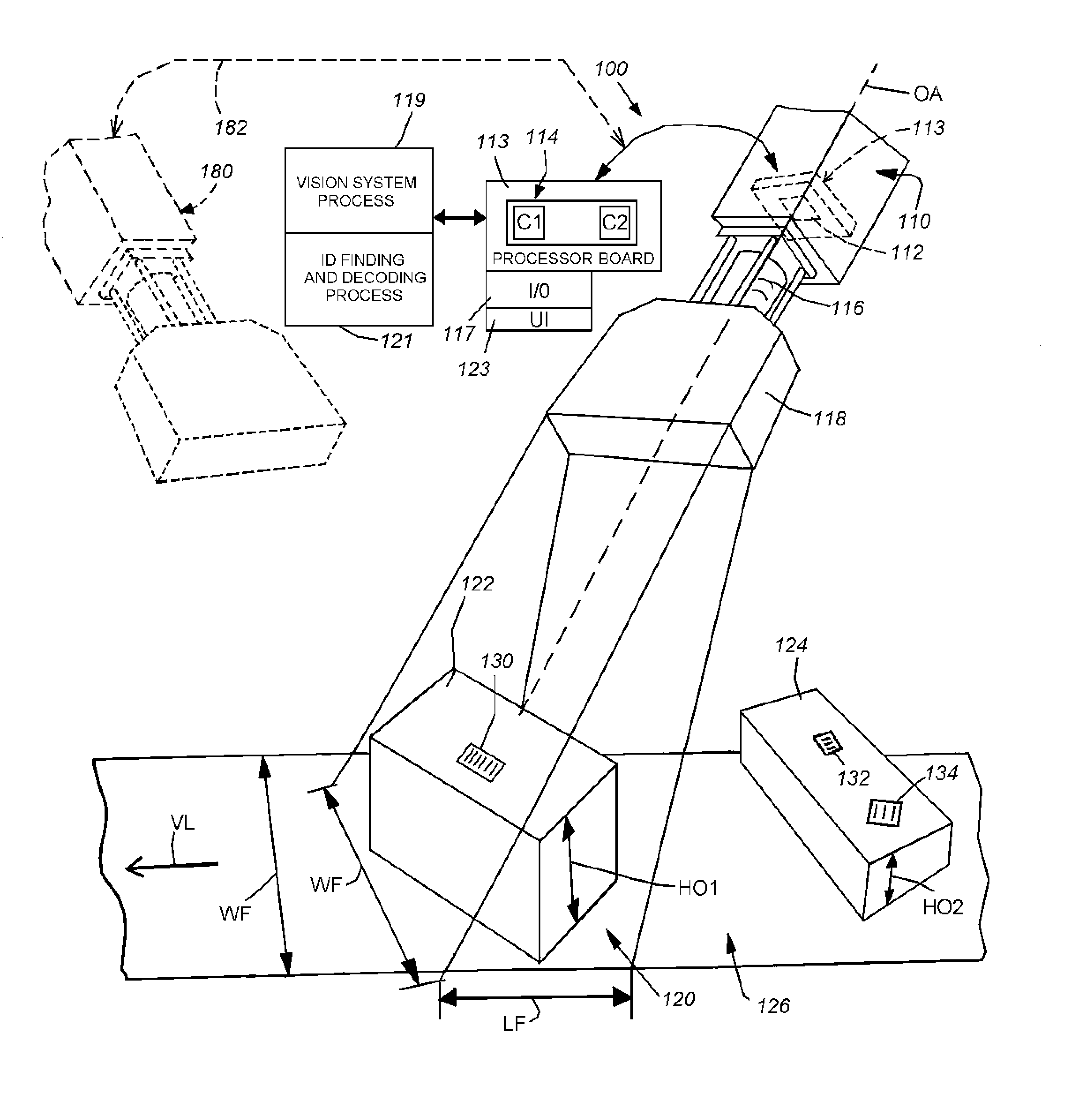
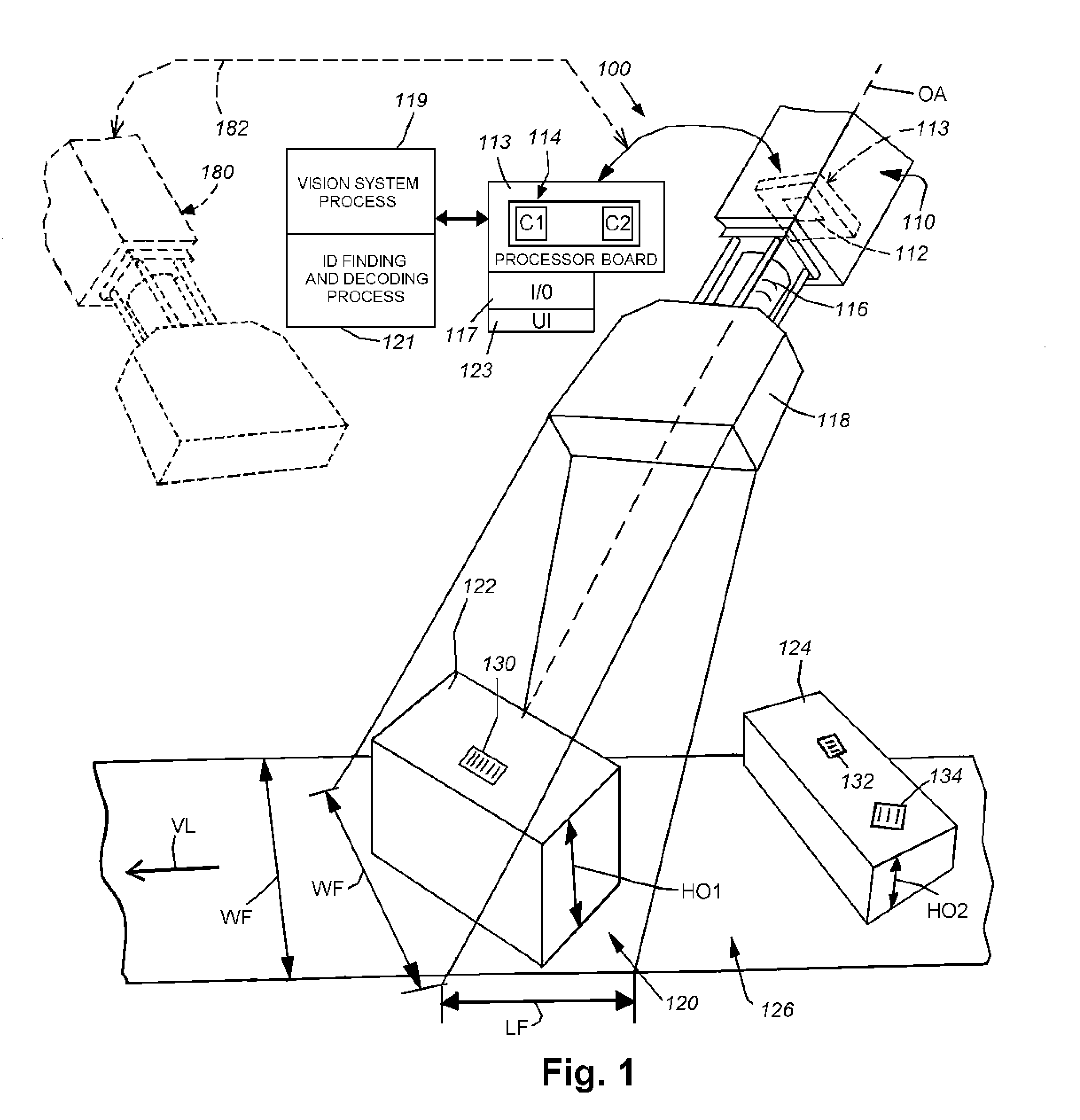
[0053]FIG. 1 depicts a vision system 100, also commonly termed a “machine vision system” according to an illustrative embodiment. The vision system 100 includes a vision system camera 110 that illustratively includes an integral (and / or internal) processor arrangement 114. This processor arrangement 114 allows image data acquired by an imager (for example a CMOS or CCD sensor) 112 (shown in phantom) to be processed so as to analyze information within the acquired image. The imager 112 resides on an associated imager circuit board (also shown in phantom) 113, described further below The processor arrangement 114 in this embodiment includes a multi-core architecture, including at least two separate (discrete) processing cores C1 and C2 that can be provided to a single circuit die (i.e. chip) according to an embodiment. The processor 114 resides on a processor or “main” board 115, also described further below. Likewise, an interconnected input / output (I / O) board 117 a...


PUM


Abstract

This invention provides a vision system camera, and associated methods of operation, having a multi-core processor, high-speed, high-resolution imager, FOVE, auto-focus lens and imager-connected pre-processor to pre-process image data provides the acquisition and processing speed, as well as the image resolution that are highly desirable in a wide range of applications. This arrangement effectively scans objects that require a wide field of view, vary in size and move relatively quickly with respect to the system field of view. This vision system provides a physical package with a wide variety of physical interconnections to support various options and control functions. The package effectively dissipates internally generated heat by arranging components to optimize heat transfer to the ambient environment and includes dissipating structure (e.g. fins) to facilitate such transfer. The system also enables a wide range of multi-core processes to optimize and load-balance both image processing and system operation (i.e. auto-regulation tasks).

Description

RELATED APPLICATION[0001]This application is related to commonly assigned U.S. patent application Ser. No. 13 / 645,173, entitled SYMBOLOGY READER WITH MULTI-CORE PROCESSOR, by Laurens Nunnink, et al, filed on even date herewith, the teachings of which are expressly incorporated herein by reference.FIELD OF THE INVENTION[0002]This invention relates to machine vision systems, and more particularly to vision systems capable of acquiring, processing and decoding symbology, such as barcodesBACKGROUND OF THE INVENTION[0003]Vision systems that perform measurement, inspection, alignment of objects and / or decoding of symbology (e.g. one-dimensional and two-dimensional bar codes—also termed “IDs”) are used in a wide range of applications and industries. These systems are based around the use of an image sensor (also termed an “imager”), which acquires images (typically grayscale or color, and in one, two or three dimensions) of the subject or object, and processes these acquired images using a...

Claims


Application Information

Patent Timeline
Patent Type & Authority Applications(United States)
IPC IPC(8): G06K7/14
CPCG06K7/1404G06K7/10732G06K7/10821G06K7/10831G06K7/10851G06K7/1491
Inventor JOUSSEN, MARIOKESTEN, JOERGNEGRO, JAMES A.NUNNINK, LAURENSWINZEN, FRANKREUTER, RICHARD
Owner COGNEX CORP
Why Eureka
Try Eureka