Advanced Valve Actuator With Remote Location Flow Reset

a valve actuator and remote location technology, applied in the field of valve actuators, can solve the problems that many conventional fluid control systems cannot properly handle hvac control applications, and achieve the effects of facilitating energy synchronization, saving energy, and increasing the energy efficiency of the building's hvac system

Active Publication Date: 2014-04-10
SCHNEIDER ELECTRIC BUILDINGS AMERICAS INC
View PDF18 Cites 51 Cited by
  • Summary
  • Abstract
  • Description
  • Claims
  • Application Information

AI Technical Summary

Benefits of technology

[0006]In a particular embodiment, the communications module is configured to communicate with a building management system (BMS) over a serial communications bus. Signals from the BMS may be retentively stored by the valve actuator, allowing the valve actuator to function properly if communication with the BMS is lost. Further, the valve actuator is configured such that its operation can be synchronized with the BMS, and with a building's mechanical heating, cooling, and pumping systems to increase energy efficiency of the building's HVAC system.
[0007]In certain embodiments, the minimum flow rate and the maximum flow rate can be adjusted either locally or remotely. Further, the maximum flow rate is maintained via modulation of a valve plug position by the valve actuator, wherein the maximum flow rate serves to limit the flow rate of liquid through the valve and HVAC coil to allow adequate time for heat transfer from the liquid to the HVAC coil. The maximum flow rate can be adjusted locally or remotely either to save energy in two-pipe water temperature changeover systems, or to compensate for piping and coil degradation. Alternatively, the maximum flow rate can be adjusted locally or remotely either to facilitate energy synchronization with the chillers and boiler, or to prevent coil overflow and maintain energy-efficient temperature differentials.
[0008]In embodiments of the invention, the minimum flow rate is maintained via modulation of a valve plug position by the valve actuator, wherein the minimum flow rate serves to prevent freezing of the liquid in the HVAC coil while minimizing energy consumption, and, in certain embodiments, may be used to decrease energy usage by the building's mechanical equipment, including chillers and boilers, by maintaining a minimum load on the equipment to allow operation at the most efficient operating level. In alternate embodiments, the minimum flow rate serves to maintain a minimum temperature differential across the valve inlet and outlet.

Problems solved by technology

For example, with conventional fluid control systems, the control valves may have a maximum flow setting that can be locally set, but is not adjustable from a remote location.
Further, many conventional fluid control systems cannot properly handle HVAC control applications involving two pipe changeover heating / cooling water systems, seasonal changeovers, and energy synchronization with a building's centrifugal chillers and condensing boilers, or with the building management system (BMS).

Method used


Image

  • Advanced Valve Actuator With Remote Location Flow Reset
  • Advanced Valve Actuator With Remote Location Flow Reset
  • Advanced Valve Actuator With Remote Location Flow Reset

Examples


Embodiment Construction

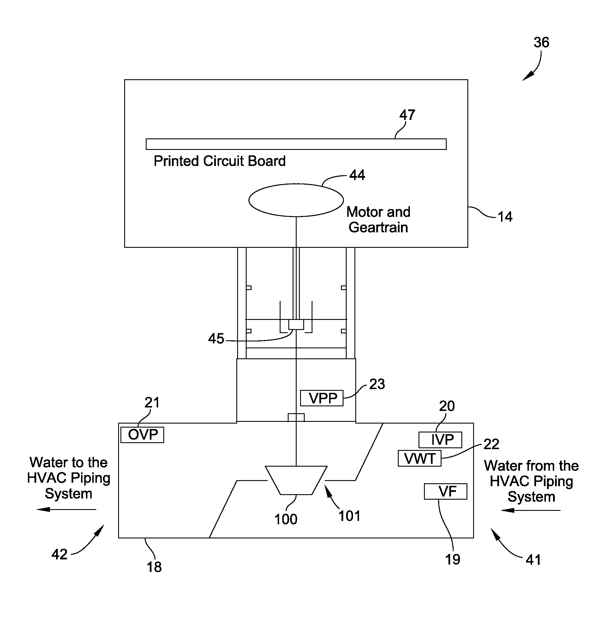
[0029]Most of the embodiments described hereinbelow illustrate how aspects of the invention may be employed in HVAC applications. However, nothing contained herein is intended to limit the invention to HVAC applications. One of ordinary skill in the art will recognize that, as implied above, aspects of the invention have applicability in a variety of commercial and industrial settings, including, but not limited to, electrical power generation, chemical manufacturing, food and beverage processing, liquid gas supply and disposal, water supply and disposal, and the like. Further, Applicants note that, while some of the drawings described below have particular applicability to HVAC systems, other drawings are illustrative of embodiments having applicability across a range of fluid control systems.

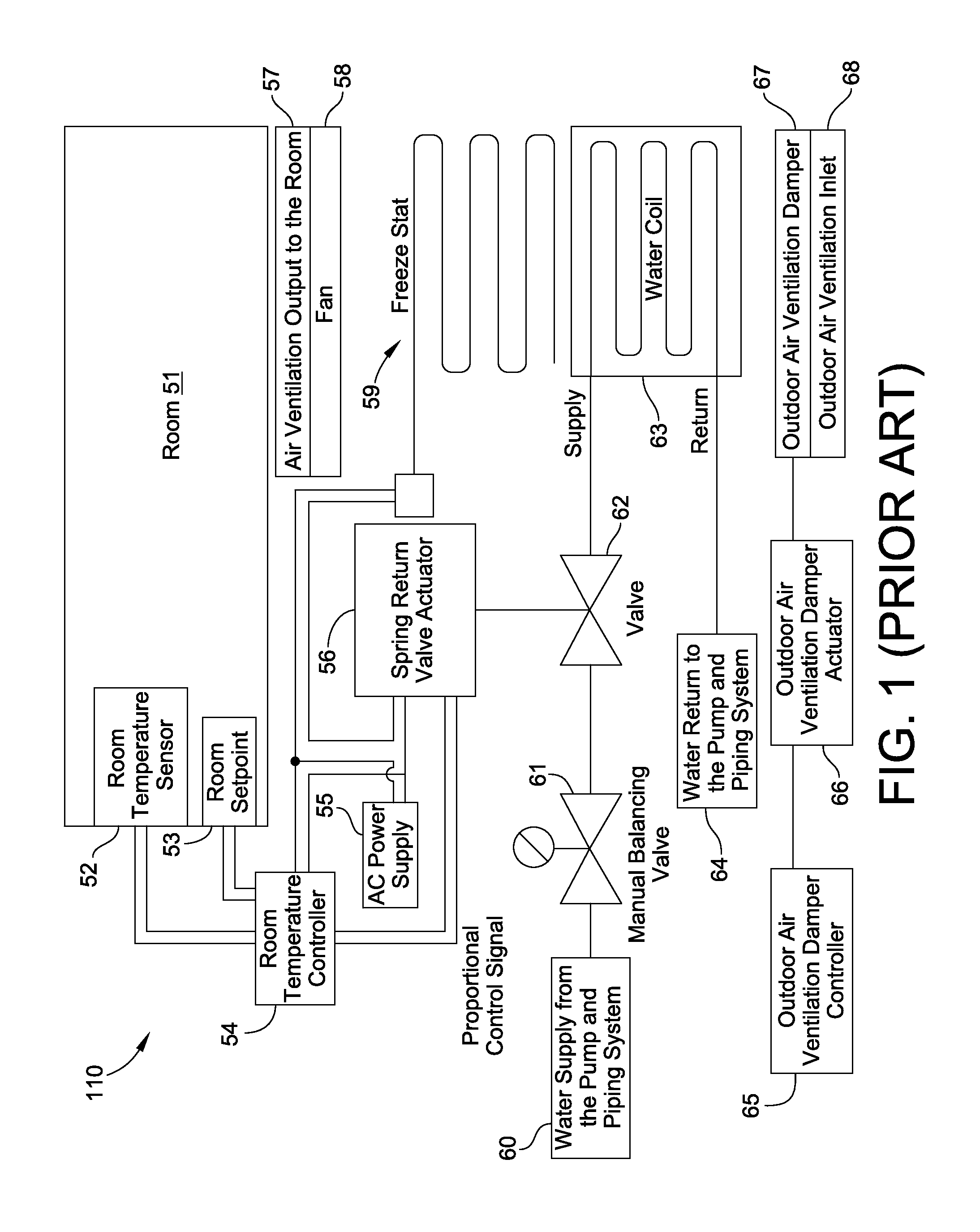
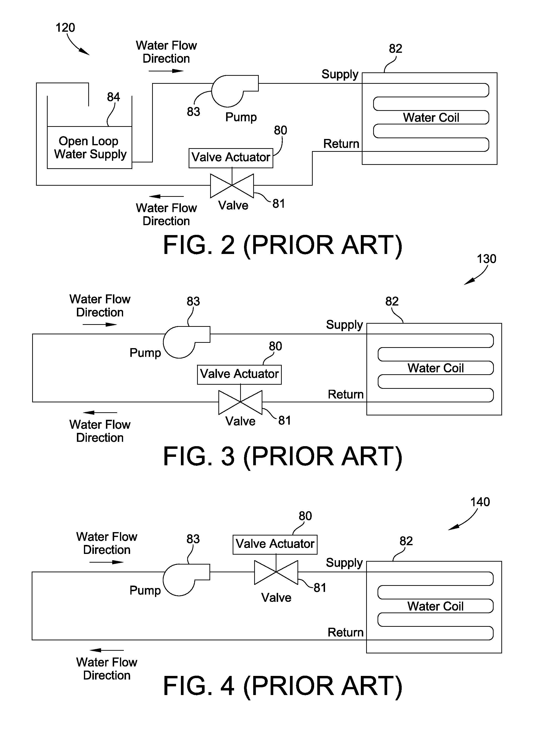
[0030]FIGS. 1-4 are schematic illustrations showing various embodiments of HVAC systems provided in the prior art. For example, FIG. 1 is a schematic diagram showing a conventional HVAC system...


PUM


Abstract

An fluid control valve and actuator assembly includes a valve configured to control a flow of liquid, and a valve actuator configured to control opening and closing of the valve, and further configured to provide both a maximum flow rate and a minimum flow rate of the liquid through the valve. In a particular embodiment, the valve actuator has a communications module configured to facilitate communication with the valve actuator over a network, and further configured to allow both remote monitoring of the flow through the valve, and remote control of the valve actuator.

Description

FIELD OF THE INVENTION[0001]This invention generally relates to valves and valve actuators, and more particularly, to valves and valve actuators configured to be controlled electronically.BACKGROUND OF THE INVENTION[0002]Many types of commercial and industrial systems involve processes in which liquids are supplied via fluid control systems that may include a variety of both pumping assemblies and control valves. These fluid control systems include, but are not limited to, those used in electrical power stations, chemical manufacturing operations, food and beverage processing, liquid gas supply and disposal, water supply and disposal, heating, ventilation, and air conditioning (HVAC) systems, etc. Improving the control mechanisms for the various components of these fluid control systems may reduce energy usage and increase the efficiency of these systems.[0003]For example, with conventional fluid control systems, the control valves may have a maximum flow setting that can be locally...

Claims


Application Information

Patent Timeline
Patent Type & Authority Applications(United States)
IPC IPC(8): F16K31/02
CPCF24F11/89F02M59/466F16K31/04F16K31/46F24D1/00G05D7/0635Y10T137/776Y10T137/7759Y10T137/7761F24D19/1015G05D7/0623
Inventor BURT, ALAN
Owner SCHNEIDER ELECTRIC BUILDINGS AMERICAS INC
Why Eureka
Try Eureka