System and method for delivering spark to an engine

a technology of spark ignition and system, which is applied in the direction of machines/engines, mechanical equipment, automatic control of ignition, etc., can solve the problems of reducing the efficiency of the ignition system, increasing the charging time of the coil, and reducing the fuel economy of the engine, so as to improve the fuel economy and/or emissions of the engine, reduce the cost of fuel consumption, and improve the effect of combustion stability

Active Publication Date: 2014-04-17
FORD GLOBAL TECH LLC
View PDF19 Cites 16 Cited by
  • Summary
  • Abstract
  • Description
  • Claims
  • Application Information

AI Technical Summary

Benefits of technology

[0003]An engine may be operated with a lean air-fuel mixture or diluted (e.g., via exhaust gas recirculation (EGR)) to improve engine fuel economy and / or emissions. However, combustion stability may be reduced when an engine is operated with a lean or diluted mixture. One way to improve combustion stability for an engine that is operated lean may be to increase spark energy. Spark energy may be increased via increasing the inductance of a coil supplying spark to the engine via a spark plug. Nevertheless, increasing coil inductance can increase coil charging time, and higher inductance coils may reduce ignition system efficiency for conditions when increased amounts of spark energy may not be desired (e.g., during combustion of a stoichiometric mixture). These and other short comings of single coil ignition systems may be overcome by supplying spark to a spark plug via two ignition coils. The two ignition coils may be charged and / or discharged at different times to increase spark duration and energy, but operating two ignition coils for each spark plug at different times may significantly raise a number of controller outputs and wires. Consequently, a dual coil per spark plug system may improve combustion stability, but it may also increase system cost, complexity, and assembly time.
[0005]By encoding ignition coil commands, it may be possible to reduce a number of conductors in an engine ignition system. In one example, ignition coil commands for one ignition coil are based on pulse widths that are greater than a first predetermined time. Ignition coil commands for a second ignition coil are based on pulse widths that are less than a second predetermined time. The two different pulse widths may be transmitted over a single conductor to operate two ignition coils supplying energy to a single spark plug.
[0006]In another example, commands for a first ignition coil may be transmitted over a first conductor while commands for a second ignition coil may be transmitted over a second conductor. The second conductor may also carry commands for a plurality of other ignition coils supplying energy to spark plugs in other engine cylinders. Thus, fewer conductors carrying ignition coil signals than ignition coils may be incorporated into an ignition system. As a result, ignition system wiring complexity may be reduced.
[0007]The present description may provide several advantages. In particular, the approach reduces ignition system wiring complexity. Further, the approach may reduce ignition system assembly time. Further still, the approach may reduce ignition system cost.

Problems solved by technology

However, combustion stability may be reduced when an engine is operated with a lean or diluted mixture.
Nevertheless, increasing coil inductance can increase coil charging time, and higher inductance coils may reduce ignition system efficiency for conditions when increased amounts of spark energy may not be desired (e.g., during combustion of a stoichiometric mixture).
Consequently, a dual coil per spark plug system may improve combustion stability, but it may also increase system cost, complexity, and assembly time.
Further, the approach may reduce ignition system assembly time.
Further still, the approach may reduce ignition system cost.

Method used


Image

  • System and method for delivering spark to an engine
  • System and method for delivering spark to an engine
  • System and method for delivering spark to an engine

Examples


Embodiment Construction

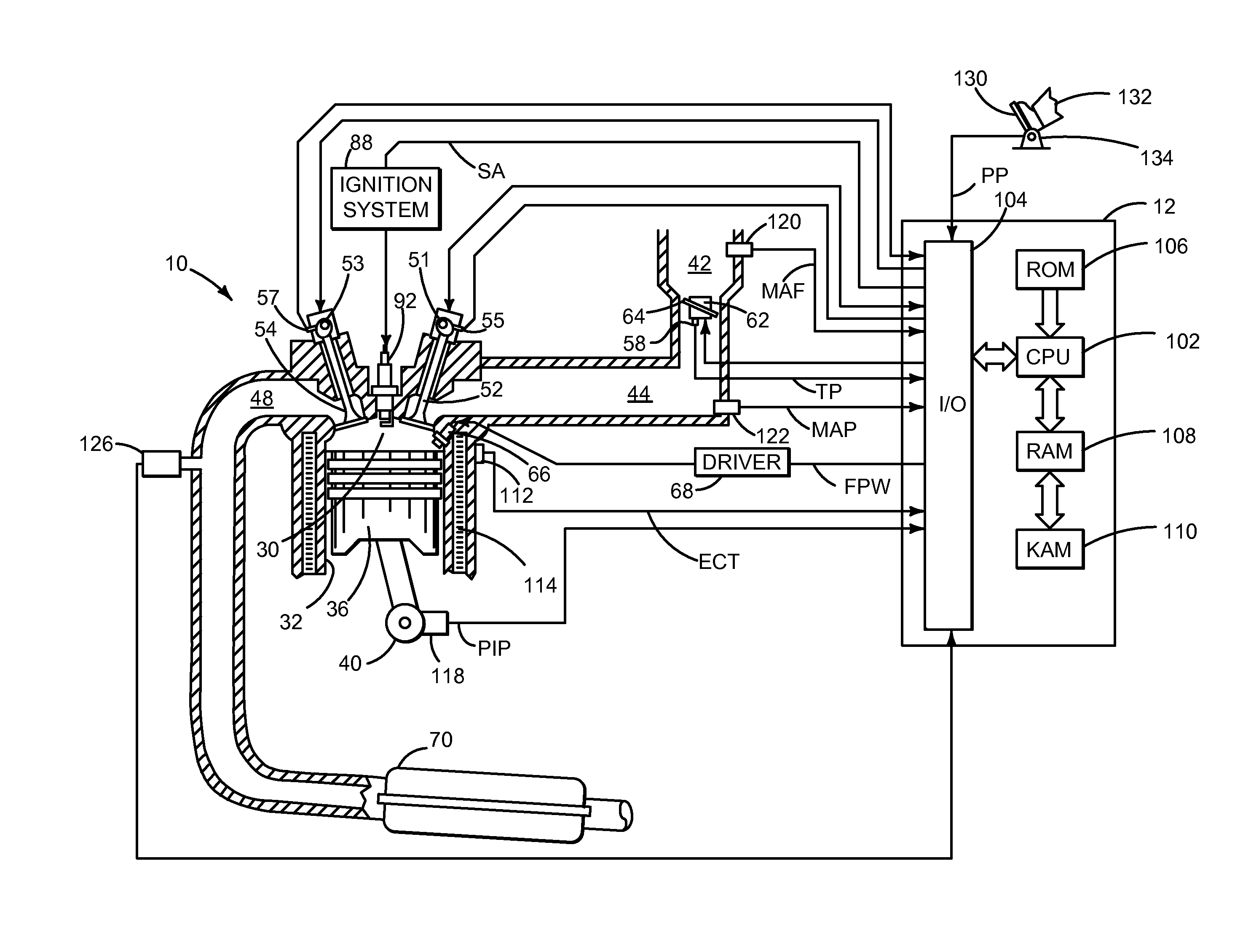
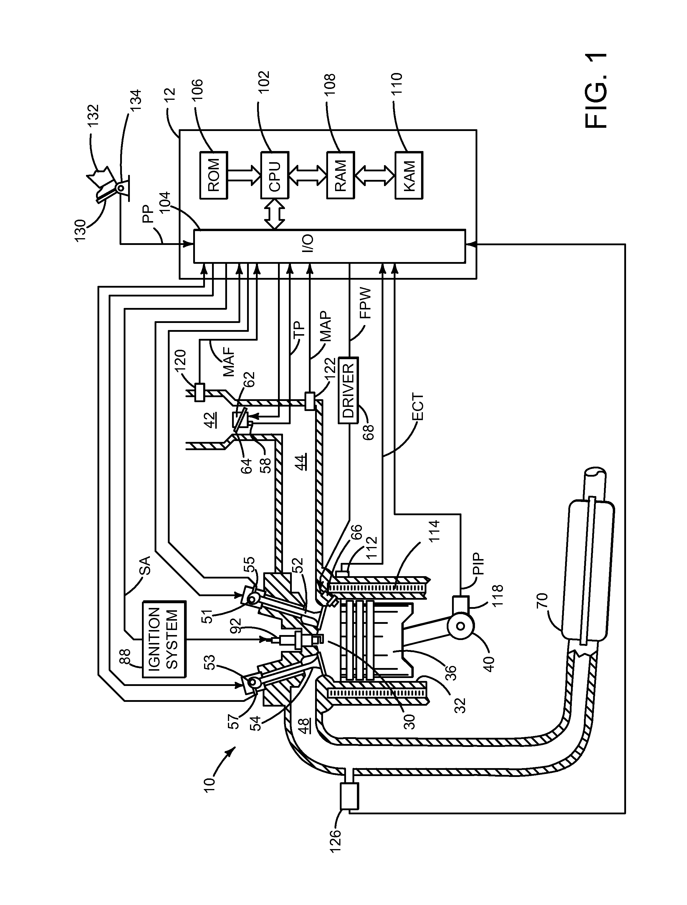
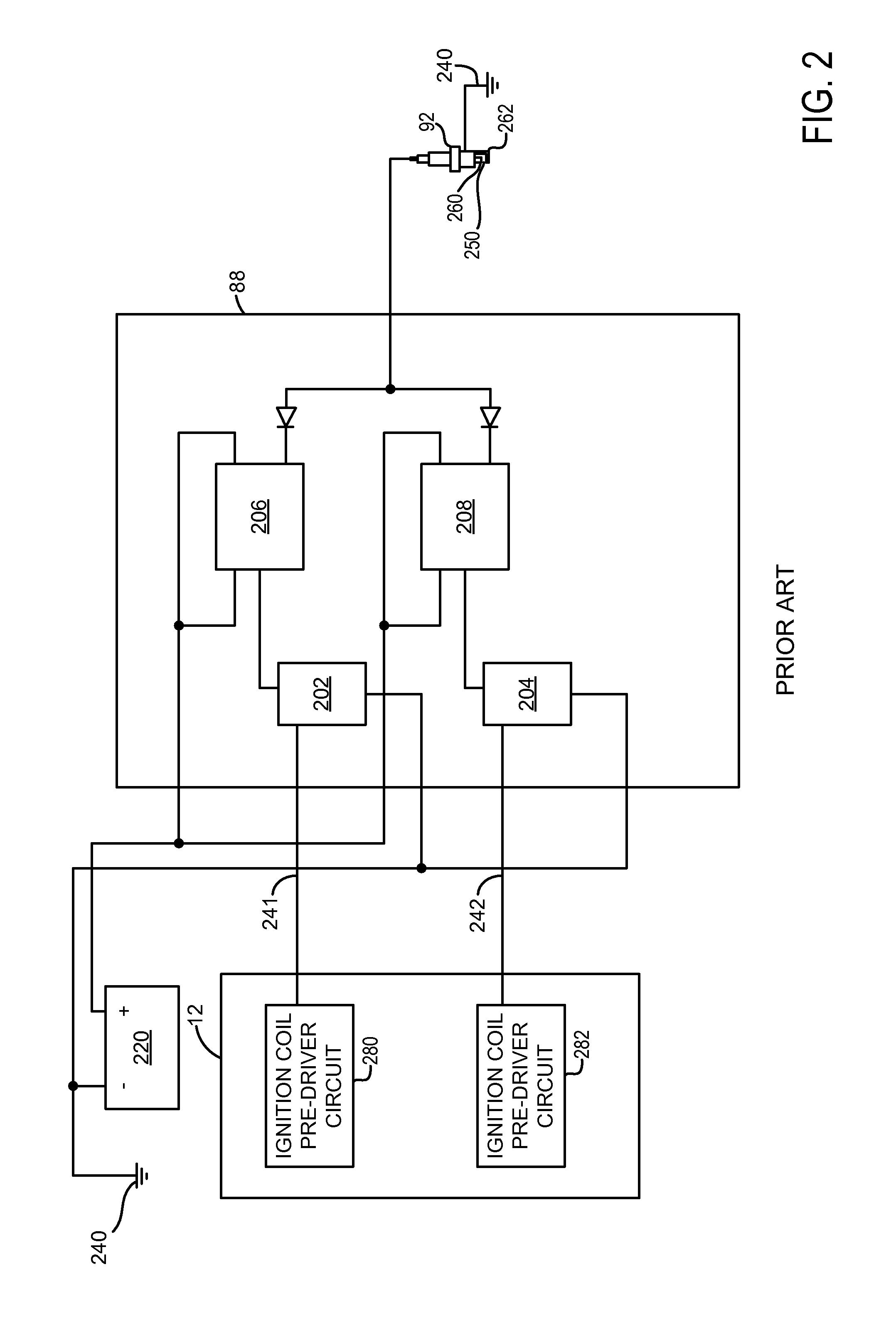
[0020]The present description is related to supplying energy to a spark ignition engine spark plug. In one non-limiting example, a control signal is supplied over a single wire. Two coils may be individually operated at different times in response to the control signal. Thus, instead of two wires supplying control signals to two ignition coils, a single wire may be utilized to perform the same function. In this way, a number of controller outputs may be reduced. Further, fewer wires may be used within the system as compared to other multiple coil systems. FIGS. 1, 3, and 4 show example ignition systems. FIG. 2 shows a prior art ignition system. The systems of FIGS. 1, 3, and 4 may provide spark energy as is shown in FIGS. 5 and 6. Example ignition system control signals are shown in FIGS. 7 and 8. Finally, FIG. 9 shows an example method for supplying energy to a single spark plug via two ignition coils.

[0021]Referring to FIG. 1, internal combustion engine 10, comprising a plurality ...


PUM


Abstract

A system and method for delivering spark to an engine is disclosed. In one example, a single conductor carries a spark signal that is indicative of a desired spark advance for a plurality of ignition coils. The system and method may reduce wiring complexity for spark plugs that are supplied energy via two ignition coils.

Description

CROSS REFERENCE TO RELATED APPLICATIONS[0001]The present application claims priority to U.S. Provisional Patent Application No. 61 / 714,058 filed on Oct. 15, 2012, the entire contents of which are incorporated herein by reference for all purposes.FIELD[0002]The present description relates to a system and method for delivering spark to a spark ignited engine. The system and method may be particularly useful for engines that operate lean or with dilute mixtures.BACKGROUND AND SUMMARY[0003]An engine may be operated with a lean air-fuel mixture or diluted (e.g., via exhaust gas recirculation (EGR)) to improve engine fuel economy and / or emissions. However, combustion stability may be reduced when an engine is operated with a lean or diluted mixture. One way to improve combustion stability for an engine that is operated lean may be to increase spark energy. Spark energy may be increased via increasing the inductance of a coil supplying spark to the engine via a spark plug. Nevertheless, in...

Claims


Application Information

Patent Timeline
Patent Type & Authority Applications(United States)
IPC IPC(8): F02P5/145
CPCF02P5/145F02P3/04F02P3/045F02P3/0456F02P15/008F02P3/02F02P1/086F02P9/002F02P15/08
Inventor CZEKALA, MICHAEL DAMIANHUBERTS, GARLAN J.QU, QIUPING
Owner FORD GLOBAL TECH LLC
Why Eureka
Try Eureka