
Integrated circuit device

a circuit device and integrated circuit technology, applied in the direction of dc-dc conversion, power conversion systems, instruments, etc., can solve the problems of failure to protect the device, reduce the withstanding voltage level of the field-effect transistor, and not enable the power source voltage to be quickly boosted up to the operating voltage, so as to ensure the protection of the device and increase the energy loss

Inactive Publication Date: 2014-04-17
THE UNIV OF TOKYO
View PDF3 Cites 24 Cited by
  • Summary
  • Abstract
  • Description
  • Claims
  • Application Information

AI Technical Summary

Benefits of technology

The invention provides an integrated circuit device that can quickly boost the power source voltage and supply it to the integrated circuit, while protecting the device. This is achieved by including a first boost converter and a third boost converter. The device includes a NAND-type flash memory with a plurality of flash memory cells, and a control voltage is specified for each flash memory cell to enable faster and more efficient voltage application during reading and writing operations. Overall, the device improves the speed and accuracy of the integrated circuit's power source voltage.

Problems solved by technology

A heavy load for boost-up, however, does not enable the power source voltage to be quickly boosted up to the operating voltage.
This technique, however, decreases the withstanding-voltage level of the field-effect transistor.
This fails to protect the field-effect transistor and thereby results in failed protection of the device.

Method used


Image

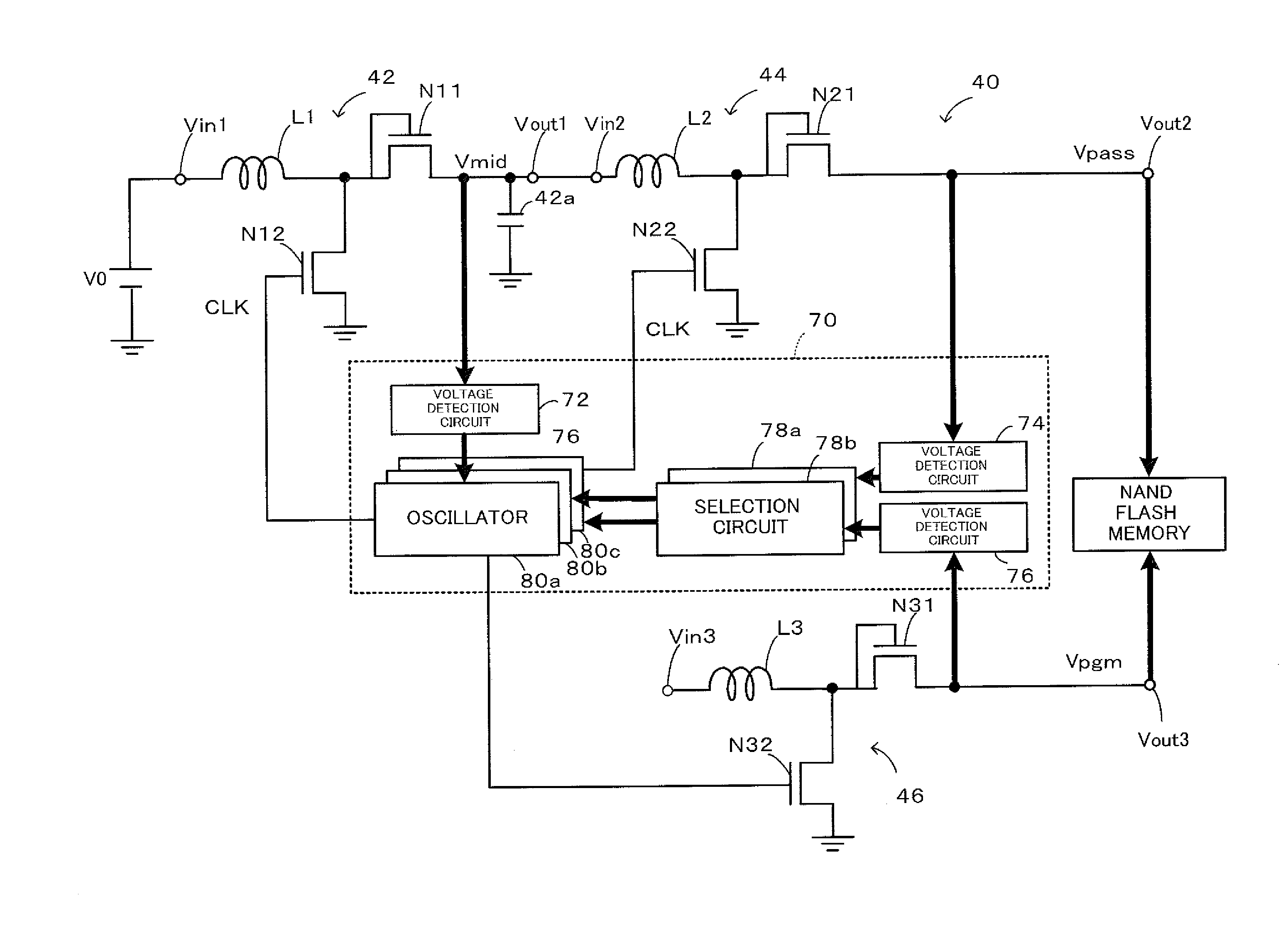
  • Integrated circuit device
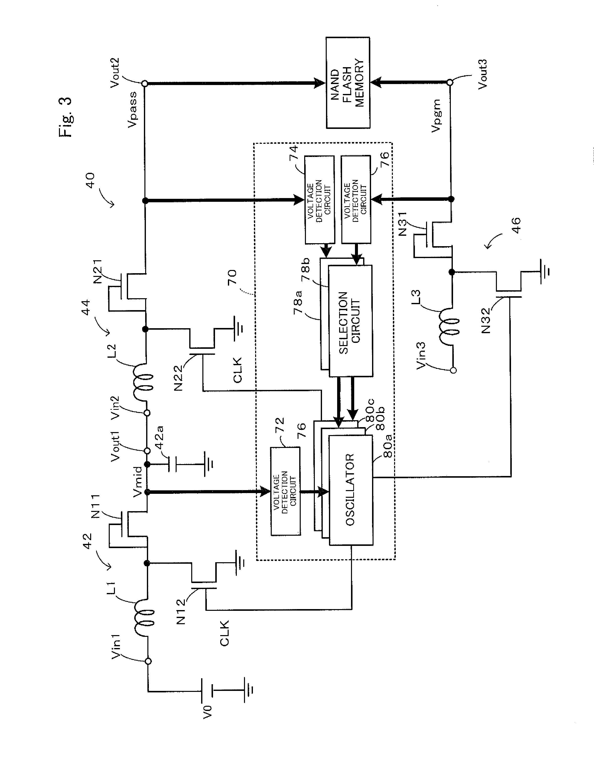
  • Integrated circuit device
  • Integrated circuit device

Examples


Embodiment Construction

[0024]The following describes the invention with reference to embodiments.

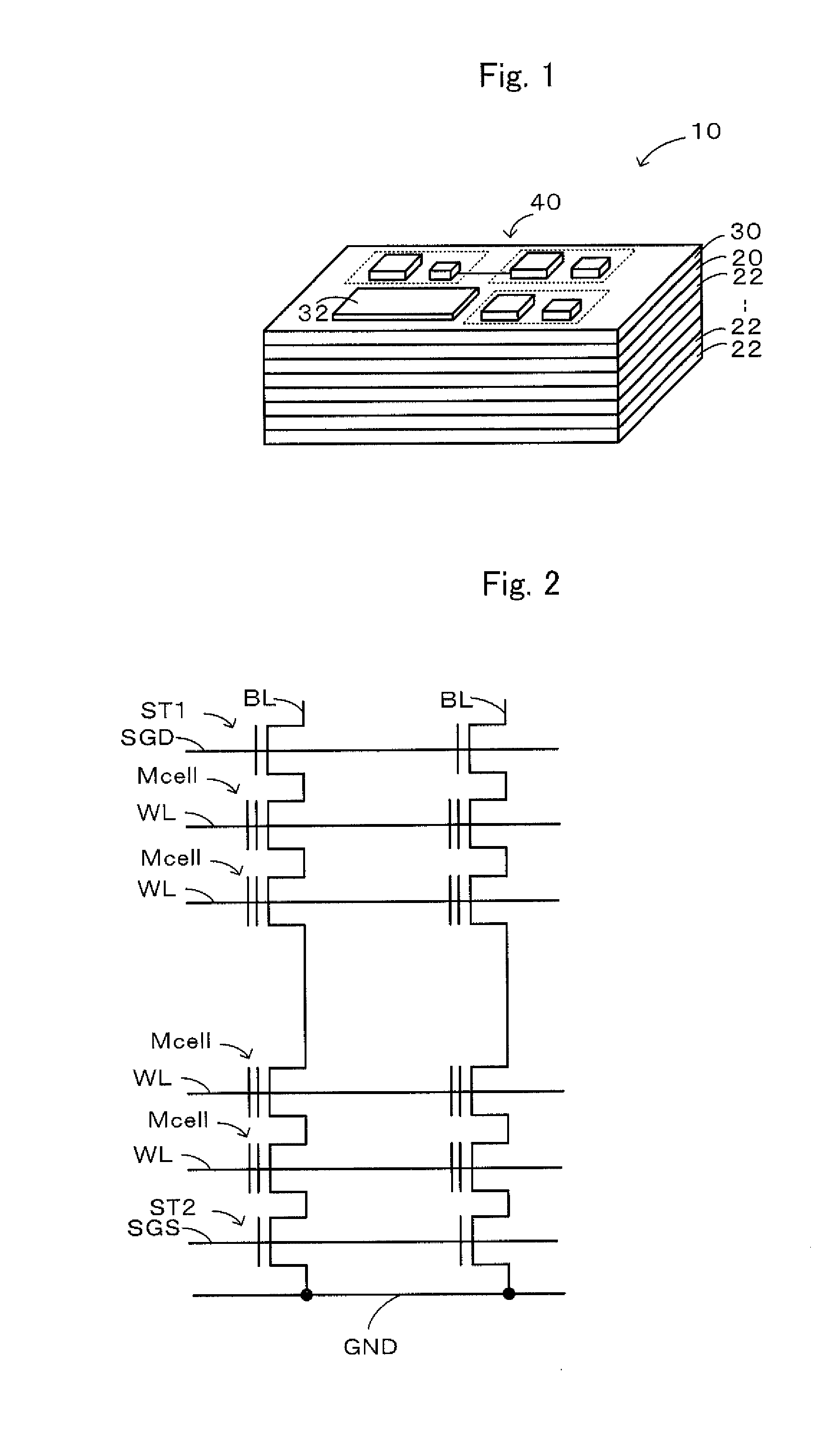
[0025]FIG. 1 is a block diagram illustrating the schematic configuration of an SSD (Solid Stated Disk 19 as an internal storage device of a computer according to one embodiment of the invention. The SSD 10 includes: a DRAM chip 20 as a silicon chip equipped with a DRAM (Dynamic Random Access Memory); a plurality of stacked flash memory chips 22 provided as silicon chips, each being equipped with a NAND-type flash memory; and an interposer 30 placed on the top-most face. A voltage V0 (for example, 1.6 V, 1.8 V or 2.0 V) as a power source voltage is supplied from a non-illustrated external power source to the SSD 10. According to this embodiment, the DRAM mounted on the DRAM chip 20 operates at the voltage V0. The flash memory mounted on the flash memory chip 22 has a voltage V1 (for example, 9.0 V, 10.0 V or 11.0 V) as a read voltage and a voltage V2 (for example, 18 V, 20 V or 22 V) as a write voltage. Non-ill...


PUM


Abstract

A booster circuit is configured, such that: in response to a reading request for reading data from a flash memory, when a voltage of an output terminal detected by a voltage detection circuit is not higher than a voltage, an oscillator outputs a control clock signal of predetermined on time and off time to a transistor of a boost converter to perform switching control of the transistor; and when the voltage detection circuit detects that the voltage of the output terminal reaches a voltage, an oscillator outputs a control clock signal of an on time and an off time input from a selection circuit to a transistor of a boost converter to perform switching control of the transistor.

Description

TECHNICAL FIELD[0001]The present invention relates to an integrated circuit device and more specifically to an integrated circuit device that includes: an integrated circuit chip equipped with an integrated circuit; and an interposer equipped with a booster supply circuit which is capable of boosting up a power source voltage supplied from a power source side and supplying the boosted-up voltage to the integrated circuit of the integrated circuit chip.BACKGROUND ART[0002]This type of the integrated circuit device has been proposed to include a plurality of flash memory chips, each being equipped with a flash memory, where the flash memory of each flash memory chip is divided into a plurality of banks and data is read and written in parallel from the respective flash memory chips while being read and written by memory interleaving (see, for example, Non Patent Literature 1). This proposed device enables high-speed data reading and writing by this operation.CITATION LISTNon Patent Lit...

Claims


Application Information

Patent Timeline
Patent Type & Authority Applications(United States)
IPC IPC(8): H02M3/155G11C16/30
CPCG11C16/30H02M3/155G11C16/06G11C16/26G11C16/3418H02M3/158H02M1/007
Inventor TAKEUCHI, KENHATANAKA, TERUYOSHIISHIDA, KOICHIYASUFUKU, TADASHITAKAMIYA, MAKOTOSAKURAI, TAKAYASU
Owner THE UNIV OF TOKYO
Learn More