Power-Saving Driver Circuit for Providing a Bias Current or Driving a Current-Driven Load

a driver circuit and current-driven load technology, applied in the direction of electric variable regulation, process and machine control, instruments, etc., can solve the problems of not only wasteful dissipation of power, need for an additional cooling element, and large amount of power waste, so as to reduce power consumption, reduce power loss, and increase efficiency

Active Publication Date: 2014-04-17
SOURCE PHOTONICS
View PDF6 Cites 12 Cited by
  • Summary
  • Abstract
  • Description
  • Claims
  • Application Information

AI Technical Summary

Benefits of technology

[0008]The present circuit advantageously provides a low-voltage, power-saving driver circuit that can be used to drive current-driven devices such as laser diodes or light emitting diodes (LEDs) in optical and / or optoelectronic transmitters and / or transceivers. By utilizing the present driving circuit, the voltage provided to a current-driven load such as a laser diode can have a minimum value sufficient to bias the load, thereby eliminating the power loss in conventional driver circuits (e.g., a load caused by a forward voltage drop across one or more current-driven devices). Thus, the present power-saving driving circuit increases efficiency and / or minimizes power consumption in comparison to conventional drivers for laser diodes.

Problems solved by technology

In conventional circuits (e.g., laser driving circuits) that provide a bias current to a laser diode or other current-driven load, a considerable amount of power may be wasted since the laser diode operates at an operating voltage (e.g., 1.8V) that is less than the bias voltage provided by or to the driving circuit (e.g., 3.3V).
This dissipation of power is not only wasteful, but it generates thermal energy, which can also adversely affect the operation(s) of nearby circuitry and / or result in a need for an additional cooling element.

Method used


Image

  • Power-Saving Driver Circuit for Providing a Bias Current or Driving a Current-Driven Load
  • Power-Saving Driver Circuit for Providing a Bias Current or Driving a Current-Driven Load
  • Power-Saving Driver Circuit for Providing a Bias Current or Driving a Current-Driven Load

Examples


Embodiment Construction

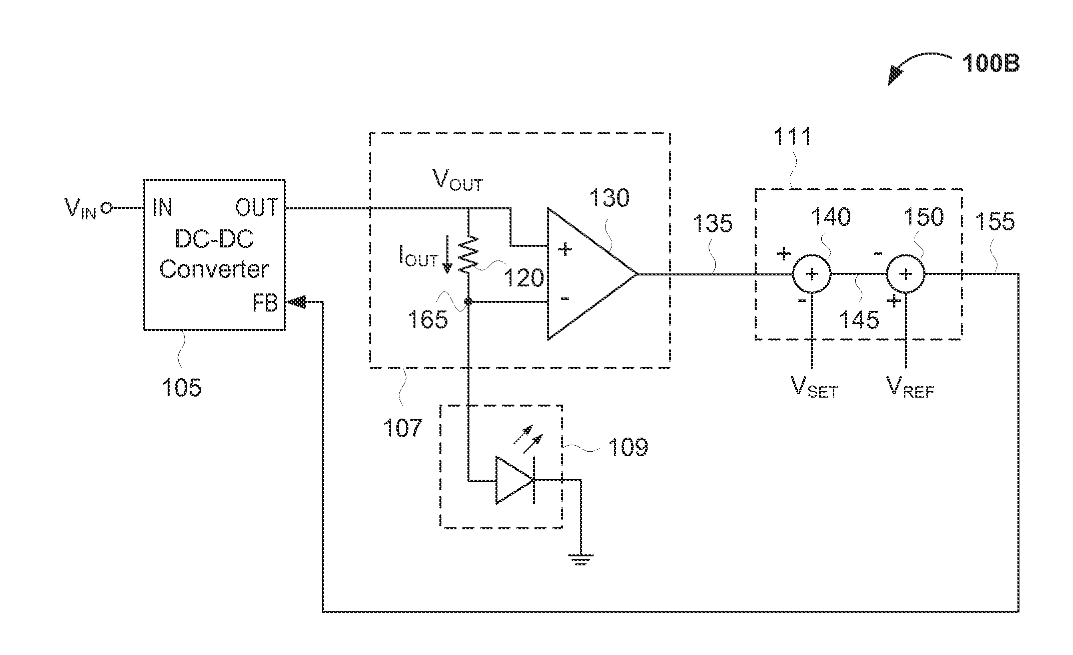
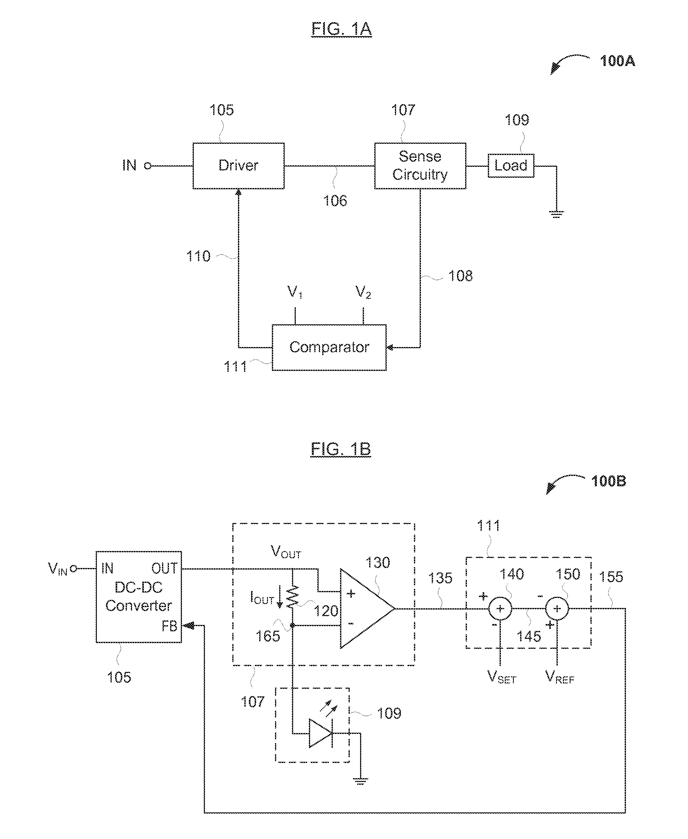
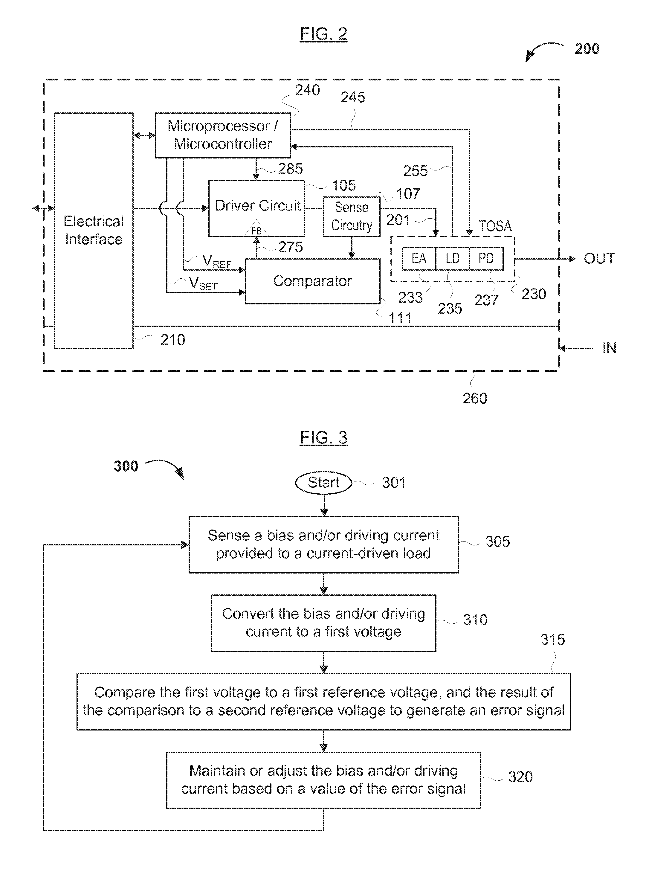
[0014]Reference will now be made in detail to various embodiments of the invention, examples of which are illustrated in the accompanying drawings. While the invention will be described in conjunction with the following embodiments, it will be understood that the descriptions are not intended to limit the invention to these embodiments. On the contrary, the invention is intended to cover alternatives, modifications and equivalents that may be included within the spirit and scope of the invention as defined by the appended claims. Furthermore, in the following detailed description, numerous specific details are set forth in order to provide a thorough understanding of the present invention. However, it will be readily apparent to one skilled in the art that the present invention may be practiced without these specific details. In other instances, well-known methods, procedures, components, and circuits have not been described in detail so as not to unnecessarily obscure aspects of th...


PUM


Abstract

Methods and circuits for providing a minimum driving voltage to a current-driven load (such as a laser diode) are disclosed. The circuit and methods may be useful for efficiently providing a bias and/or driving current to the current-driven load with minimal energy loss. The circuit generally comprises (1) a driver or voltage source configured to provide the bias and/or driving current to the current-driven load, (2) a sense circuit configured to (i) sense the bias and/or driving current and (ii) convert the bias and/or driving current to a first voltage, and (3) a comparator configured to (i) receive the first voltage and first and second reference voltages and (ii) provide a feedback/error signal to the driver or voltage source, the feedback/error signal configured to maintain or adjust the bias and/or driving current at or towards a target value.

Description

FIELD OF THE INVENTION[0001]The present invention generally relates to a circuit for driving a current driven load and / or providing a precise minimum bias current with improved (and optimally, maximum) power efficiency. More specifically, embodiments of the present invention pertain to methods and apparatuses for providing a bias and / or driving current to an optical and / or optoelectronic transmitter and / or transceiver.DISCUSSION OF THE BACKGROUND[0002]Laser diodes are current driven devices that receive a bias voltage or current from a current source. In conventional circuits (e.g., laser driving circuits) that provide a bias current to a laser diode or other current-driven load, a considerable amount of power may be wasted since the laser diode operates at an operating voltage (e.g., 1.8V) that is less than the bias voltage provided by or to the driving circuit (e.g., 3.3V).[0003]For example, the available supply voltage VCC (for example, 3.3V) is received by the driver, and the la...

Claims


Application Information

Patent Timeline
Patent Type & Authority Applications(United States)
IPC IPC(8): G05F1/46H04B10/02H01S3/10H05B44/00
CPCH05B45/395Y02B20/30
Inventor AZADEH, MOHAMMAD
Owner SOURCE PHOTONICS
Why Eureka
Try Eureka