Gas turbine diffuser blowing method and corresponding diffuser

a technology of gas turbines and diffusers, which is applied in the direction of machines/engines, stators, liquid fuel engines, etc., can solve the problems of affecting the overall balance of the cycle, affecting the stability of the cycle, and unable to achieve a reintroduction without generating additional losses

Active Publication Date: 2014-04-17
SAFRAN HELICOPTER ENGINES
View PDF2 Cites 9 Cited by
  • Summary
  • Abstract
  • Description
  • Claims
  • Application Information

AI Technical Summary

Benefits of technology

[0011]Such blowing therefore makes it possible to “stabilise” a boundary layer by making it turbulent when it is laminar, and thus to delay the separations since a turbulent boundary layer is intrinsically more stable than a laminar boundary layer. When the boundary layer is turbulent, this supply of energy delays the appearance of separations. In addition, even if the separation of the air flow is already initiated, the supply of energy can likewise enable the reattachment of the boundary layer.
[0012]The phenomenon of re-energisation according to the invention can be reinforced by the “coanda” effect which appears when a jet of air is situated close to a convex wall. This effect results in attraction of the fluid towards the wall. This “coanda” effect can be maximised depending upon the speed and the angle of ejection of the air in the region of the withdrawal.
[0018]the speed of ejection of the air during injection thereof is chosen between Mach 0.7 and 1, and the angle of ejection is chosen between 60° and 90° with respect to a normal to the injection face of the blades and / or intake end plates, in order to maximise the coanda effect.

Problems solved by technology

But this system is not optimal, since if the reintroduction of air into the diffuser can improve the stability of the compressor, diverting the air at the outlet of the impeller can cause new problems of stability.
Moreover, to effect a reintroduction without generating additional losses is difficult, because the air at the outlet of the impeller is at a lower static pressure level than that of the re-injection site.
However, it may prove necessary to discharge outside this collected air to the exterior, which is prejudicial to the overall balance of the cycle.

Method used


Image

  • Gas turbine diffuser blowing method and corresponding diffuser
  • Gas turbine diffuser blowing method and corresponding diffuser
  • Gas turbine diffuser blowing method and corresponding diffuser

Examples


Embodiment Construction

[0008]The invention seeks to combat more effectively the separation of the boundary air layer by actively stabilising this layer. In order to do this, the invention provides for re-energising the boundary layer with air at a higher pressure by a blowing / suction coupling.

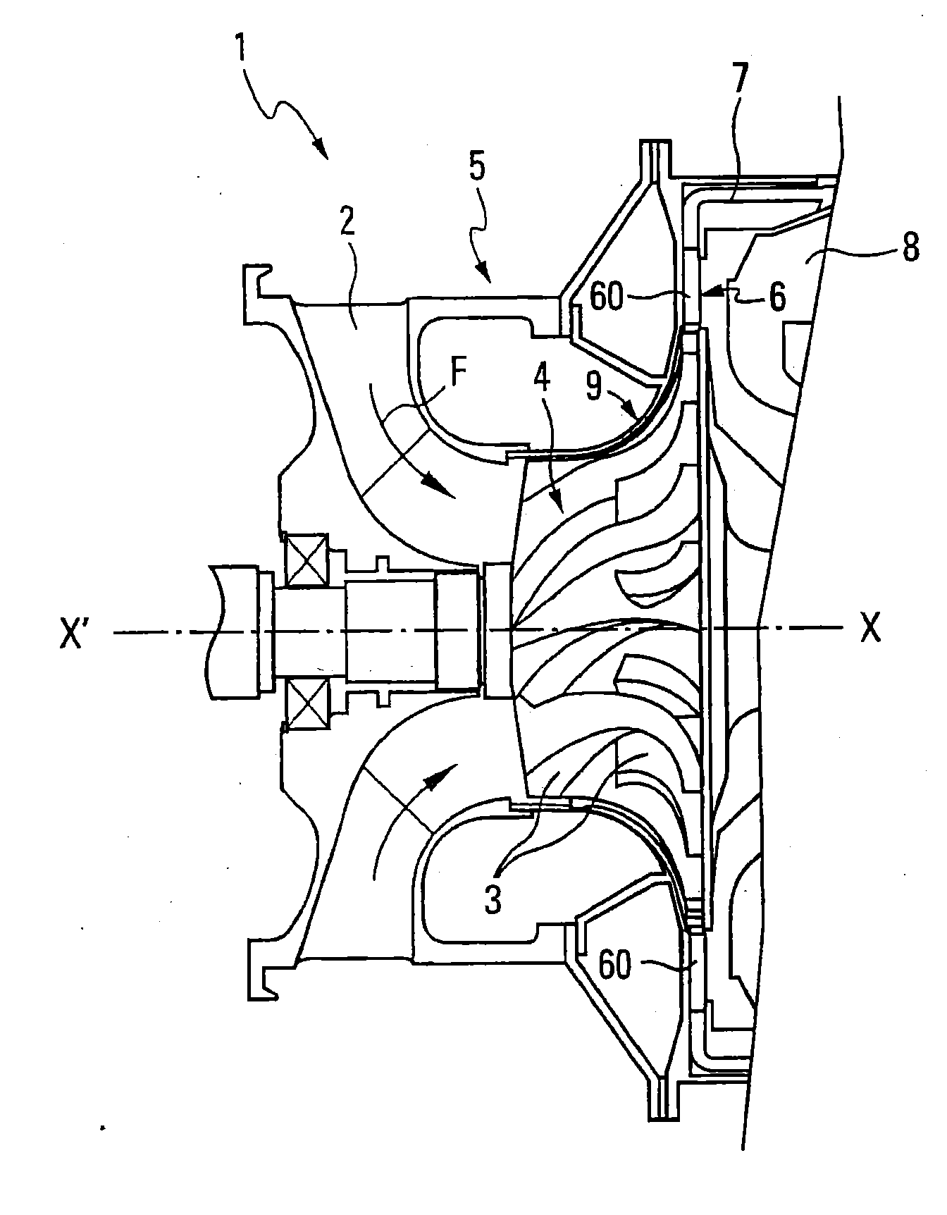
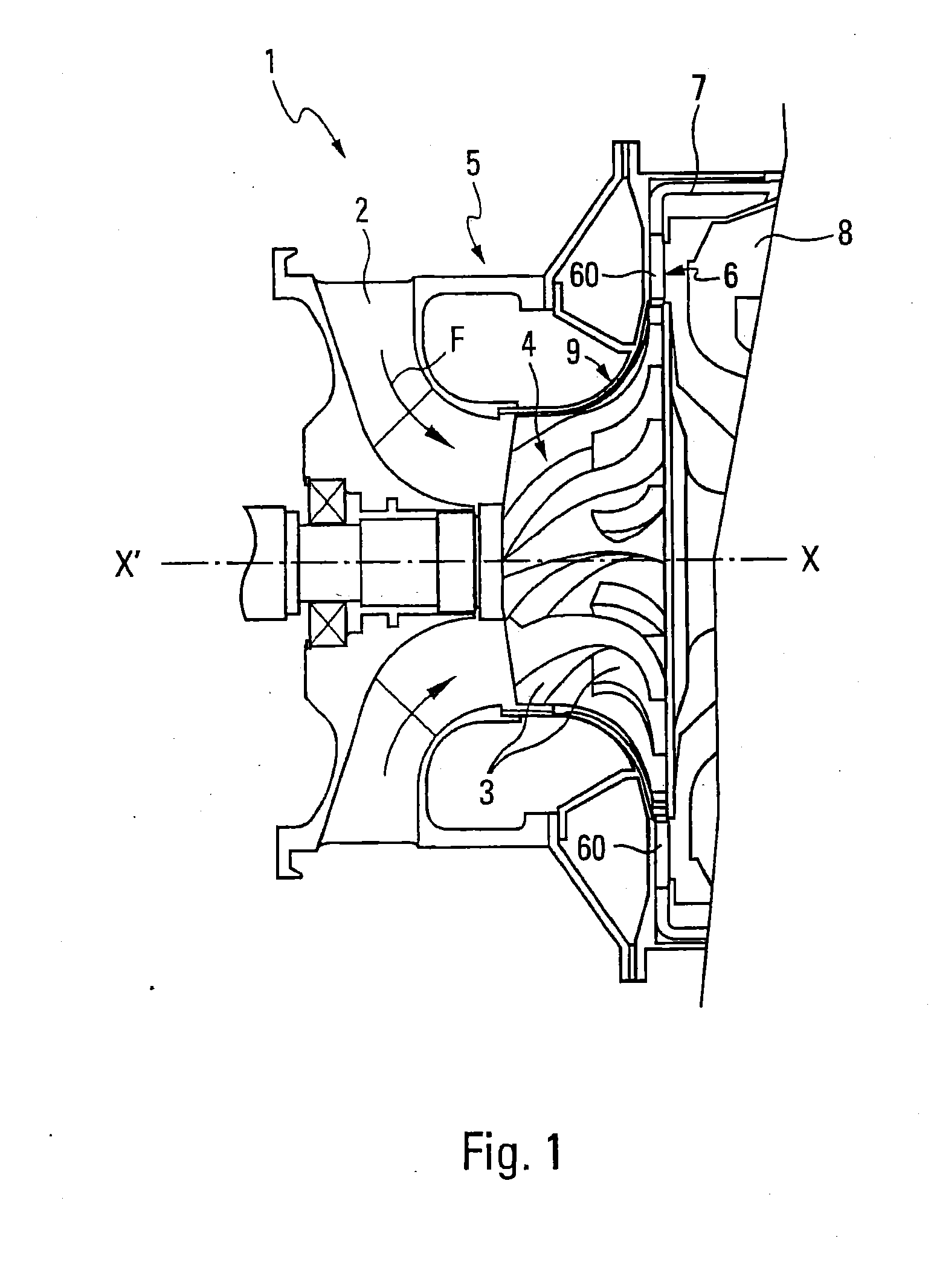
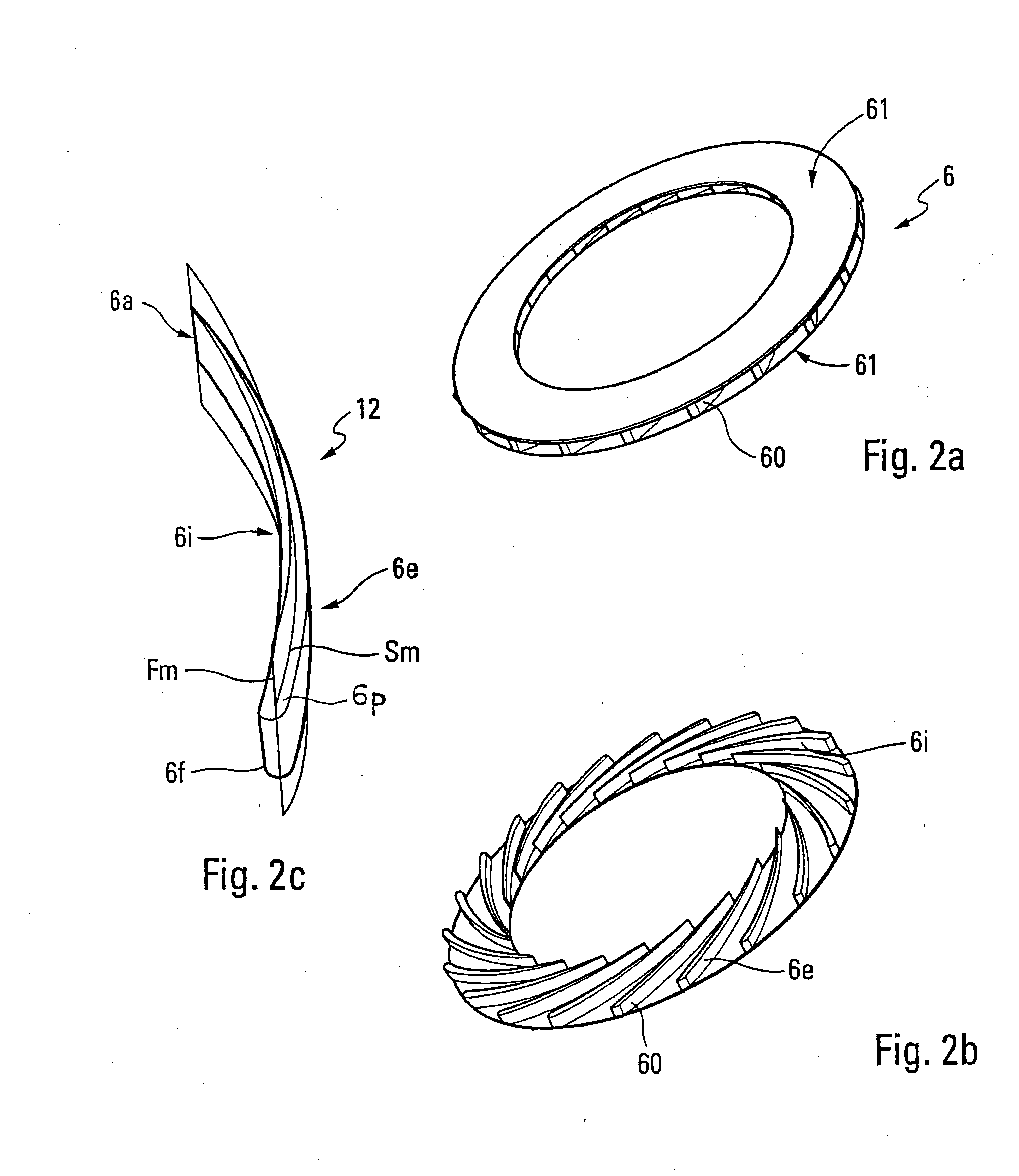
[0009]More precisely the present invention relates to a method of blowing air into a compression stage diffuser of a compressor of a gas turbine. Such a diffuser includes two end plates enclosing a plurality of circumferential blades. The air flow along the blades is effected from a leading edge to a trailing edge of the diffuser. In this method, coupling of an injection of air into the air passage upstream of the diffuser is carried out with a withdrawal of air originating from the downstream air passage via an air intake at the leading edges, upstream relative to the trailing edges situated downstream. Blowing of the injected air occurs in the air passage from upstream to downstream via this air intake. The injecti...


PUM


Abstract

A diffuser of a compressor of centrifugal or mixed type includes two end plates which enclose a plurality of regularly distributed circumferential blades, and at least one transverse upstream passage produced in lower or upper surfaces of the blades. An injection / withdrawal coupling is achieved by a recirculation of a stream in an air passage of the diffuser on the basis of injection of air from at least one point in a leading edge zone of an upstream side of the diffuser. Blowing of air is then effected in at least one groove formed along a lateral flank of each blade by withdrawal of the air stream in a region of a trailing edge. Thereby, effectively separation of the air in a boundary layer in a gas turbine compressor diffuser is realized by re-energizing the boundary layer with air at a higher pressure by a suction / re-injection coupling.

Description

TECHNICAL FIELD[0001]The invention relates to a method of blowing air in a compression stage diffuser of a gas turbine, in particular in compressors of the centrifugal or mixed type. A mixed compressor may be understood to be a compressor structured at the impeller outlet such that the air stream forms an angle of between 0 and 90° relative to a radial direction. The invention also relates to a compressor diffuser suitable for implementing such a process.[0002]The field of the invention is that of operation of compressors and improvement of their performance, in particular of the surge margin. The performance is in particular sensitive to the air flow coming from the impeller of the compressor. The diffuser has the function of adjusting this flow in order to optimise the transformation of the dynamic air pressure into static pressure.[0003]In general, a diffuser is composed of inclined blades in a space formed between two end plates. The deviation produced by the blades can cause ai...

Claims


Application Information

Patent Timeline
Patent Type & Authority Applications(United States)
IPC IPC(8): F04D29/44
CPCF04D29/441F04D27/023F04D27/0238F04D29/444F04D29/682F04D29/684F05D2240/122F05D2250/52F04D27/00F04D29/44F04D29/68
Inventor PORODO, JEROME YVES FELIX GILBERTTARNOWSKI, LAURENT PIERRE
Owner SAFRAN HELICOPTER ENGINES
Why Eureka
Try Eureka