Eureka AIR delivers breakthrough ideas for toughest innovation challenges, trusted by R&D personnel around the world.

Liquid pump device

Active Publication Date: 2014-04-17
CUI MING +1
View PDF6 Cites 2 Cited by
  • Summary
  • Abstract
  • Description
  • Claims
  • Application Information

AI Technical Summary

Benefits of technology

The present invention is a liquid pump device for conveying liquid from a container. It includes a sealing design to prevent contamination and improve the usage rate of the liquid. The device is simple in structure, low cost, and disposable after being scrapped without causing damage or pollution. The device includes a soft sealed bladder for further protection and a soft rubber pressing device that requires no restoration spring. It also utilizes elastic automatic restoration and is easy to disassemble and dispose of. Overall, the liquid pump device has improved effectiveness and safety, and is environmentally friendly.

Problems solved by technology

Such liquid pump device has a defect in terms of design.
As for liquid products (for example, oil-like or water-like products) with low viscosity and good flowability, even if the container is not moved and suffers from no shock, after a period of time, the liquid remain at the outlet portion approximate the press head will also trickle under the gravity, thereby causing undesired pollution.

Method used


Image

  • Liquid pump device
  • Liquid pump device
  • Liquid pump device

Examples


first embodiment

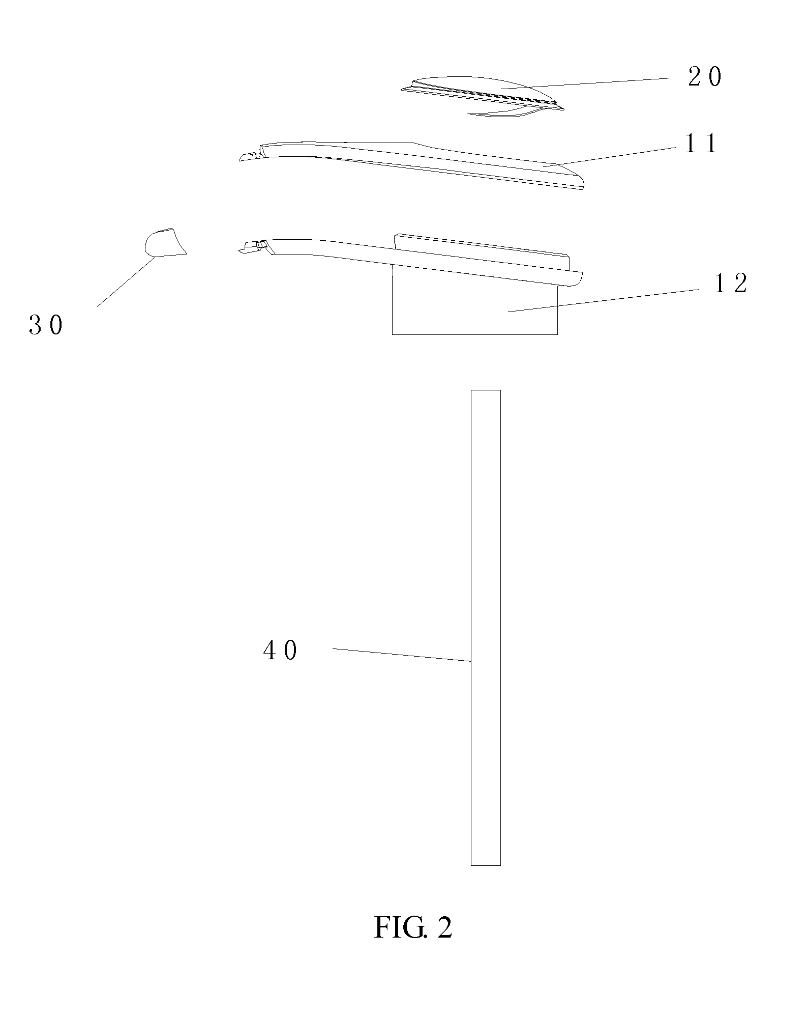
[0025]FIG. 2 and FIG. 3 illustrate a structure of the liquid pump device according to the present invention. In this embodiment, the liquid pump device comprises a pump shell body, a soft rubber pressing device 20, a sealed discharge port end cap 30, and a guiding tube 40.

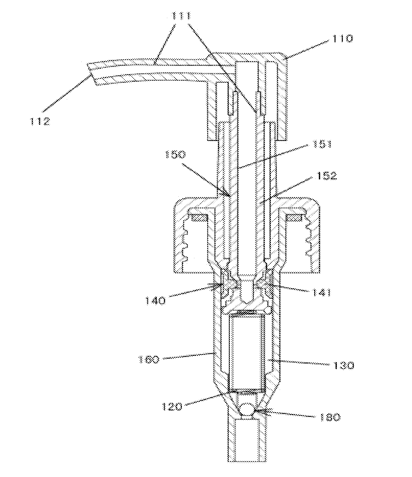
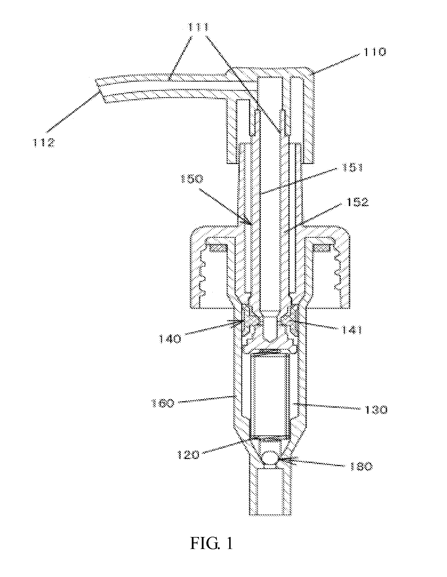
[0026]The pump shell body comprises an upper shell 11 and a lower shell 12, wherein the lower shell 12 is provided with an arc surface with an upward opening. The upper shell 11 and the lower shell 12 are connected to form a cavity and the discharge channel 15 communicated with the cavity. A flange 10 is arranged at the lower end of the arc surface of the lower shell 12, a through hole being arranged at the middle of the flange. The guiding tube 40 is arranged in the through hole, and is communicated with the cavity via the feeding channel 16.

[0027]The soft rubber pressing device 20 comprises an arc-shaped pressing sheet 1 and an integrally formed and arranged elastic support sheet 2. The soft rubber pressing devic...

second embodiment

[0034]According to the present invention, the liquid pump device further comprises a soft sealed bladder, wherein the soft sealed bladder is used to receive liquid and is arranged in the container for preventing the unused liquid from contacting with ambient environment. In addition, the liquid is not directly contained in the container, but is protected by using the soft sealed bladder in the container. Furthermore, the wall of the guiding tube is provided with a plurality of through holes arranged at different positions thereon, which achieves maximum usage rate of the liquid in the container. Such structures are especially applicable to high level cosmetics. The liquid pump device according to the present invention has advantages of simple structure, low cost, and convenience for dismantlement, easiness for disposal after being scrapped, no damages and pollution to environment.


PUM


Abstract

The present invention relates to a liquid pump device, comprising a pump shell body, a soft rubber pressing device, a discharge channel, a sealed discharge port end cap, and a guiding tube, wherein the pump shell body comprises an upper shell and a lower shell, wherein the lower shell is provided with an arc surface with an upward opening, the upper shell and the lower shell are connected to form a cavity and the discharge channel communicated with the cavity, and a flange is arranged at the lower end of the arc surface of the lower shell, a through hole being arranged at the middle of the flange; the soft rubber pressing device is snap-fit connected onto the upper shell and covers the cavity, and the soft rubber pressing device forms a cavity with the lower shell; the sealed discharge end cap is provided with at least one cut, the cut forming an invisible discharge port, and the sealed discharge cap is sleeved to an end portion of the discharge channel; and the guiding tube is arranged in the through hole of the flange, and is communicated with the cavity via the feeding channel. The invisible discharge port according to the present invention effectively prevents liquid from contamination caused by ambient environment.

Description

FIELD OF THE INVENTION[0001]The present invention relates to a liquid pump device.BACKGROUND OF THE INVENTION[0002]Liquid pump devices are typically installed at the mouths of containers, and are used for pumping liquid products inside the container out of the containers. In a typical liquid pump device, the liquid is pumped out of the container through up and down movement of the piston rod, such that the liquid is discharged from the discharge port. FIG. 1 illustrates a liquid pump device in the prior art. When a user presses the press head of the press pump, a lower one-way valve 180 is turned off, and an upper one-way valve 140 is turned on. The upper one-way valve is formed of the outer circumferential surface of a piston rod 152 and a piston member 141 installed on the circumferential surface. The outer circumferential surface of the piston rod 152 serves as a valve base, and the piston member 141 serves as a valve member. The liquid product in a liquid storage tank 130 in a c...

Claims


Application Information

Patent Timeline
IPC IPC(8): F04B53/16
CPCF04B53/16B05B15/30B05B11/026B05B11/1032B05B11/1069B05B11/1097F04B43/0063
Inventor CUI, MINGZHANG, LIAN
Owner CUI MING
Why Eureka
Eureka Blog
Learn More