Pressure control by phase current and initial adjustment at car line

Active Publication Date: 2014-04-17
VITESCO TECH USA LLC
View PDF4 Cites 47 Cited by
  • Summary
  • Abstract
  • Description
  • Claims
  • Application Information

AI Technical Summary

Benefits of technology

[0010]The pump system of the present invention is more precise than a preconfigured map control (which has a total failure of the summation of component tolerances), and does not require a pressure

Problems solved by technology

The type of pressure sensor required for a closed-loop feedback system is costly and adds components to the system.
An open-loop system for a fuel pump does not provide a measurement of pressure that is used for comparison to a desired pressure.
Known mapped contro

Method used


Image

  • Pressure control by phase current and initial adjustment at car line
  • Pressure control by phase current and initial adjustment at car line
  • Pressure control by phase current and initial adjustment at car line

Examples


Embodiment Construction

[0024]The following description of the preferred embodiment(s) is merely exemplary in nature and is in no way intended to limit the invention, its application, or uses.

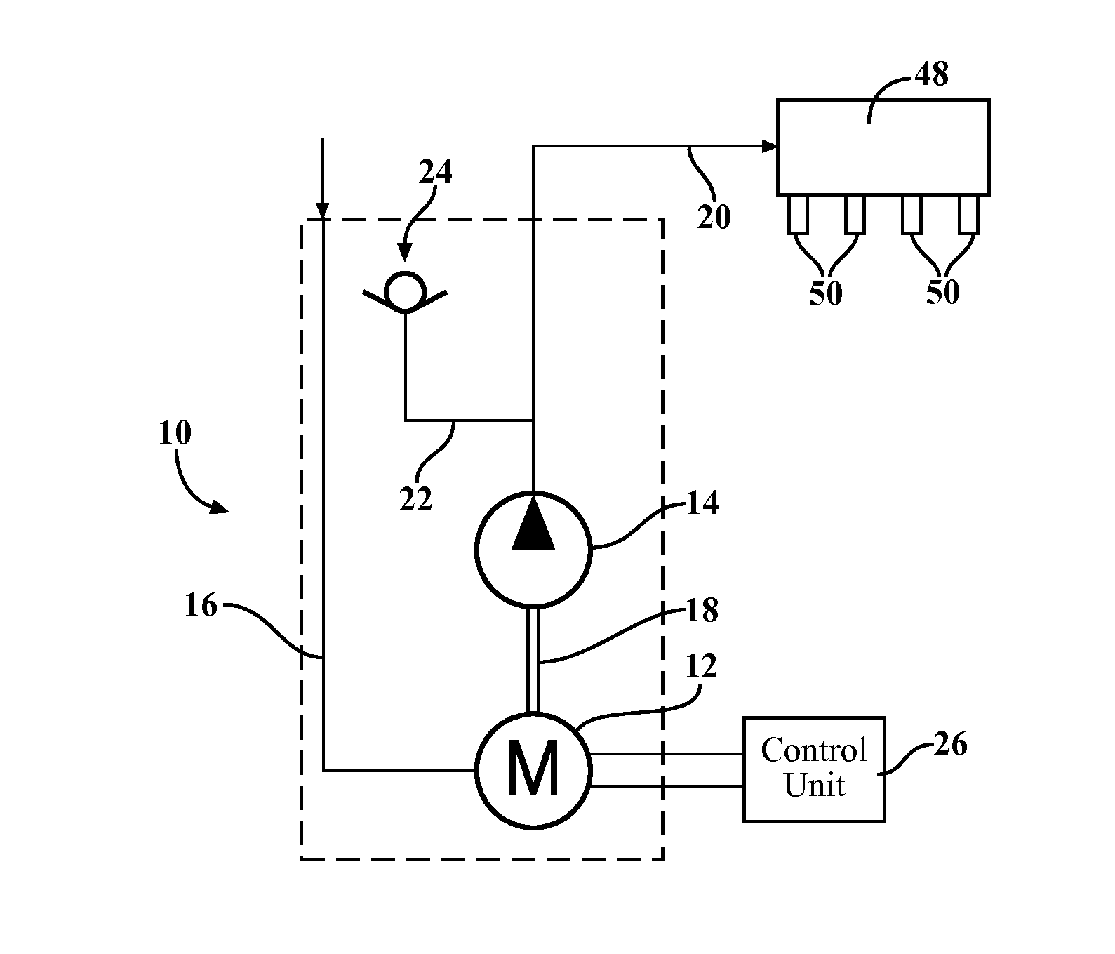
[0025]A diagram of a pump system according to the present invention is shown at 10. The pump system 10 includes a motor 12 and a device 14 for generating a pumping action, such as, but not limited to, a gerotor pump, an impeller pump, or any other mechanism suitable for creating a pumping action. The motor 12 is in fluid communication with an inlet conduit 16. The motor 12 is also connected to the device 14 through a mechanical connection 18. The device 14 is in fluid communication with an outlet conduit 20, and the outlet conduit 20 is in fluid communication with a secondary conduit 22. In fluid communication with the secondary conduit 22 is an internal calibration valve, shown generally at 24. The pump system 10 is controlled by a control unit 26. The input signal into the control unit 26 determines the nominal pres...


PUM


Abstract

A closed loop control system for a fuel pump based on characteristics of speed, pressure, and current. The pressure generated by the pump system is increased at the point in time when the pump system is working against a dead head system (i.e., coasting) to a level that a calibration valve is opened to a determined working point. By measuring the characteristic phase current as a function of the speed, the characteristic is able to be compared, with the pre-calibrated value of the hardware to perform an error compensation algorithm. The error compensation is overlaid with the standard pressure characteristic as a function of speed and phase current, and uses the pre-calibrated opening pressure value (i.e., the inflection point) of the calibration valve and/or in addition the change of the speed to the initial (first calibration), or to a sliding average therefrom.

Description

CROSS-REFERENCE TO RELATED APPLICATIONS[0001]This application claims the benefit of U.S. Provisional Application No. 61 / 713,183 filed Oct. 12, 2012. The disclosure of the above application is incorporated herein by reference.FIELD OF THE INVENTION[0002]The invention relates generally to a closed loop control system for a fuel pump which also includes calibration functionality.BACKGROUND OF THE INVENTION[0003]Fuel pumps are commonly used to transfer fuel to an injection system for an engine. It is common for a fuel pump to be driven by a type of motor, such as an electric motor. The operation of the fuel pump and motor are typically controlled by some type of closed-loop feedback system, where pressure is monitored, and the speed of the pump is adjusted based on a comparison of the measured pressure to the desired pressure. These types of closed-loop feedback control systems require a pressure sensor to monitor the pressure. The type of pressure sensor required for a closed-loop feed...

Claims


Application Information

Patent Timeline
IPC IPC(8): F04D13/06F04C14/24
CPCF04C14/24F04D13/0686F02D41/3082F02D41/20F02D41/221F02D41/2432F02D41/2438F02D41/2464F02D41/2496F02D41/3845F02D2041/2027F04C15/008F04D13/06
Inventor SAUSNER, ANDREASVOLKER, MARC
Owner VITESCO TECH USA LLC
Why Eureka
Try Eureka