Method for manufacturing blow molds

Active Publication Date: 2014-04-17
KRONES AG
View PDF3 Cites 4 Cited by
  • Summary
  • Abstract
  • Description
  • Claims
  • Application Information

AI Technical Summary

Benefits of technology

[0025]In another preferable embodiment, heat conduction pipes are further applied to the blow mold preform on the side facing away from the negative model, in particular directly on the carrier layer, and are by flame-spraying applied a metallic and/or ceramic coating. Such heat conduction pipes are preferably manufactured of thin-walled pipes and/or tubes to ensure good transfer of heat from the passed heat-conducting medium to the adjacent wall regions of the blow mold. The subsequent metallic and/or ceramic coating by flame-spraying improves heat transfer and serves to avoid air gaps between the wall of the blow mold preform and the heat conduction pipes.
[0026]Preferably, at least a temperature sensor, a pressure sensor, a heating element, and/or a cooling element are further applied to the side of the blow mold preform facing away from the negative model, in particular directly on the carrier layer, and are by flame-spraying applied a metallic and/or ceramic coating. This allows for easy integration of sensors and actively operated heating elements

Problems solved by technology

Additional technical problems are caused by functional cavities within the blow mold, for example, in the form of ducts

Method used


Image

  • Method for manufacturing blow molds
  • Method for manufacturing blow molds
  • Method for manufacturing blow molds

Examples


Example

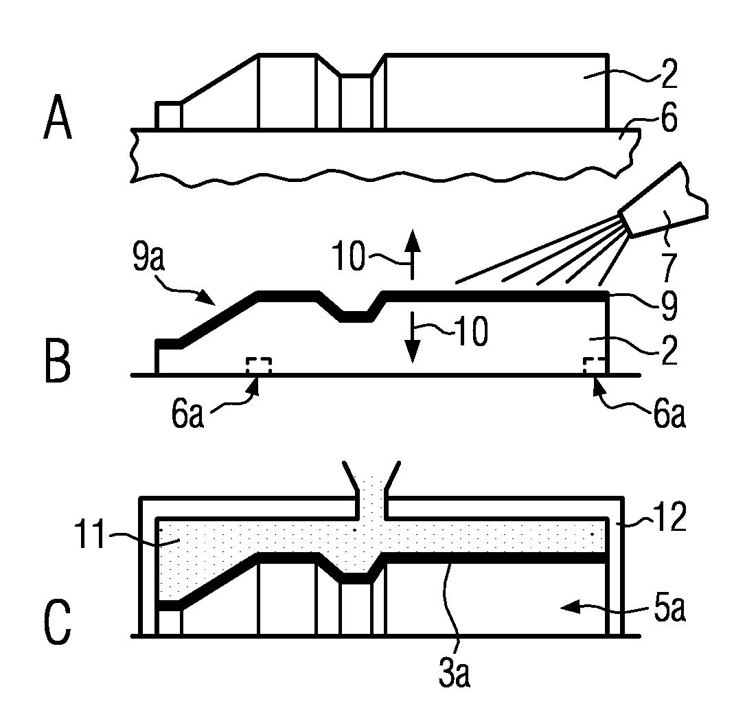
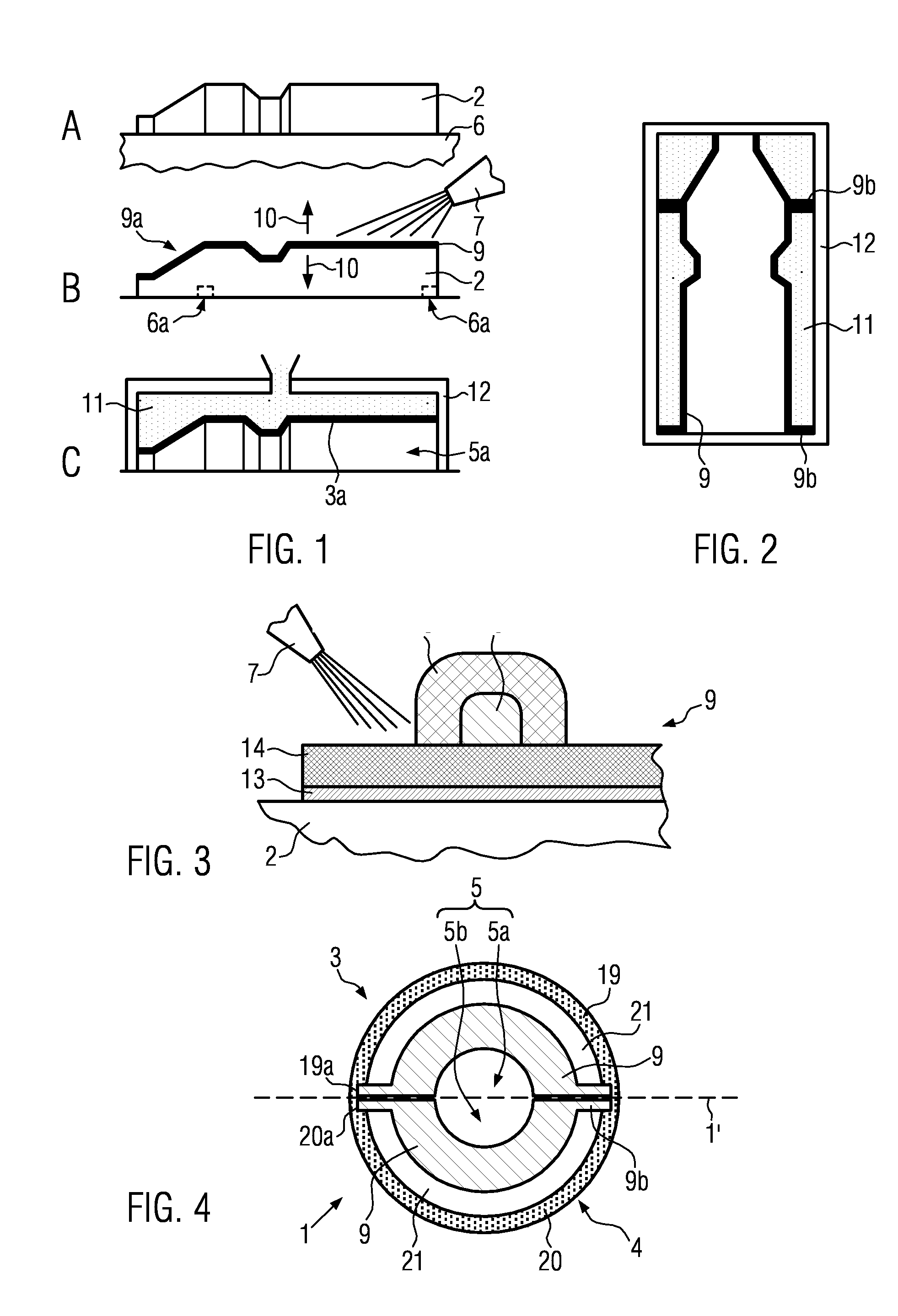
[0041]As shown in FIG. 1 with reference to FIG. 4, a preferred embodiment of the method according to the disclosure for manufacturing blow molds 1 comprises a step marked with an A, in which a negative model 2 of a blow mold segment 3 to be manufactured is provided, for example, a blow mold half. The negative model 2 is a body substantially corresponding to a negative mold of the inner wall 3a of the blow mold segment 3 to be manufactured and therefore corresponds to the positive mold of the partial cavity 5a of the blow mold 1 enclosed by this blow mold segment 3. Preferably, the blow cavity 5 of the blow mold 1 is composed of two complementary partial cavities 5a, 5b, which are symmetrical with respect to a parting plane 1′ of the blow mold 1. The blow cavity can particularly preferably also be composed of three complementary partial cavities, namely two partial cavities 5a, 5b as well as an associated base member (not shown).

[0042]As shown, the negative model 2 can be made, for e...


PUM

PropertyMeasurementUnit
Pressureaaaaaaaaaa
Electrical conductivityaaaaaaaaaa
Electrical resistanceaaaaaaaaaa

Abstract

A method for manufacturing segmented blow molds for plastic containers, where blow mold preforms are manufactured by flame-spraying at least one metal-containing and/or ceramic-containing layer on a negative model of at least one segment of the blow mold to be manufactured, and the at least one layer is then detached from the negative model, thereby providing a particularly simple and repeatable manufacturing of blow molds.

Description

CROSS-REFERENCE TO RELATED APPLICATION[0001]The present application claims the benefit of priority of German Application No. 102012218928.9, filed Oct. 17, 2012. The entire text of the priority application is incorporated herein by reference in its entirety.FIELD OF THE DISCLOSURE[0002]The disclosure relates to a method for manufacturing blow molds for plastic containers, in particular plastic bottles, a blow mold manufactured with the method and a plastic container produced with such a blow mold.BACKGROUND[0003]Plastic containers, such as plastic bottles or the like, can—as known—be produced in blow molds by stretch-blowing heated preforms. They are, for example, segmented into two halves along the major axis of the container to be blown which can be opened prior to and after stretch-blowing the plastic bottle. The blow mold halves essentially correspond to a negative of the bottle to be produced and are usually manufactured, for example, by milling, eroding and coating the inner b...

Claims


Application Information

Patent Timeline
IPC IPC(8): B29C41/08
CPCB29C41/08B29C49/48B29C49/4823B29C2049/4874B29C2049/4876B29C33/3857B29C2033/3864Y10T428/1397B29C49/487105
Inventor ALBRECHT, THOMAS
Owner KRONES AG
Why Eureka
Try Eureka