
Pellicle

Active Publication Date: 2014-04-17
SHIN ETSU CHEM CO LTD
View PDF2 Cites 7 Cited by
  • Summary
  • Abstract
  • Description
  • Claims
  • Application Information

AI Technical Summary

Benefits of technology

The present invention allows for increased light exposure area by minimizing the widths of the pellicle side bars. It also allows for manufacturing a pellicle with low rigidity by supplementing it with an outer frame, which prevents deformation or damage. Additionally, the present invention allows for precise adhesion to a photomask while maintaining the desired dimension.

Problems solved by technology

However, it has been found that, when efforts were made to narrow the widths of the pellicle side bars of IP Publication 1 as much as possible, the result was always a pellicle frame which cannot stand a practical use.
In other words, although it is expected that whatever the widths of pellicle side bars may be, so long as the designing ensures a balance between the membrane tension and the outward bias of the side bars, straight side bars should always be the result, still the fact remains that when the widths of the pellicle side bars are excessively reduced, even if straight-line side bars are obtained, the rigidity of the pellicle frame is too small so that the deformation of the pellicle frame becomes extraordinary and handling of the frame becomes difficult, and only a slight external force added to the frame could cause slacking or rippling in the pellicle membrane and hence such a pellicle frame cannot be used practically.

Method used


Image

  • Pellicle
  • Pellicle
  • Pellicle

Examples


example 1

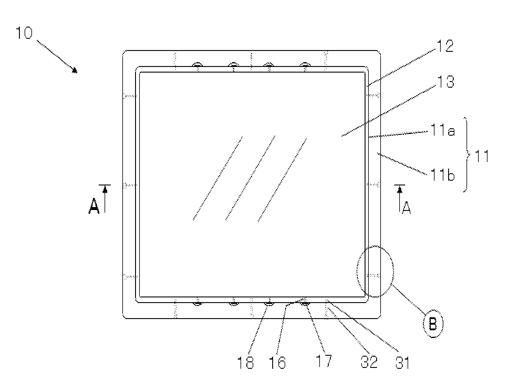
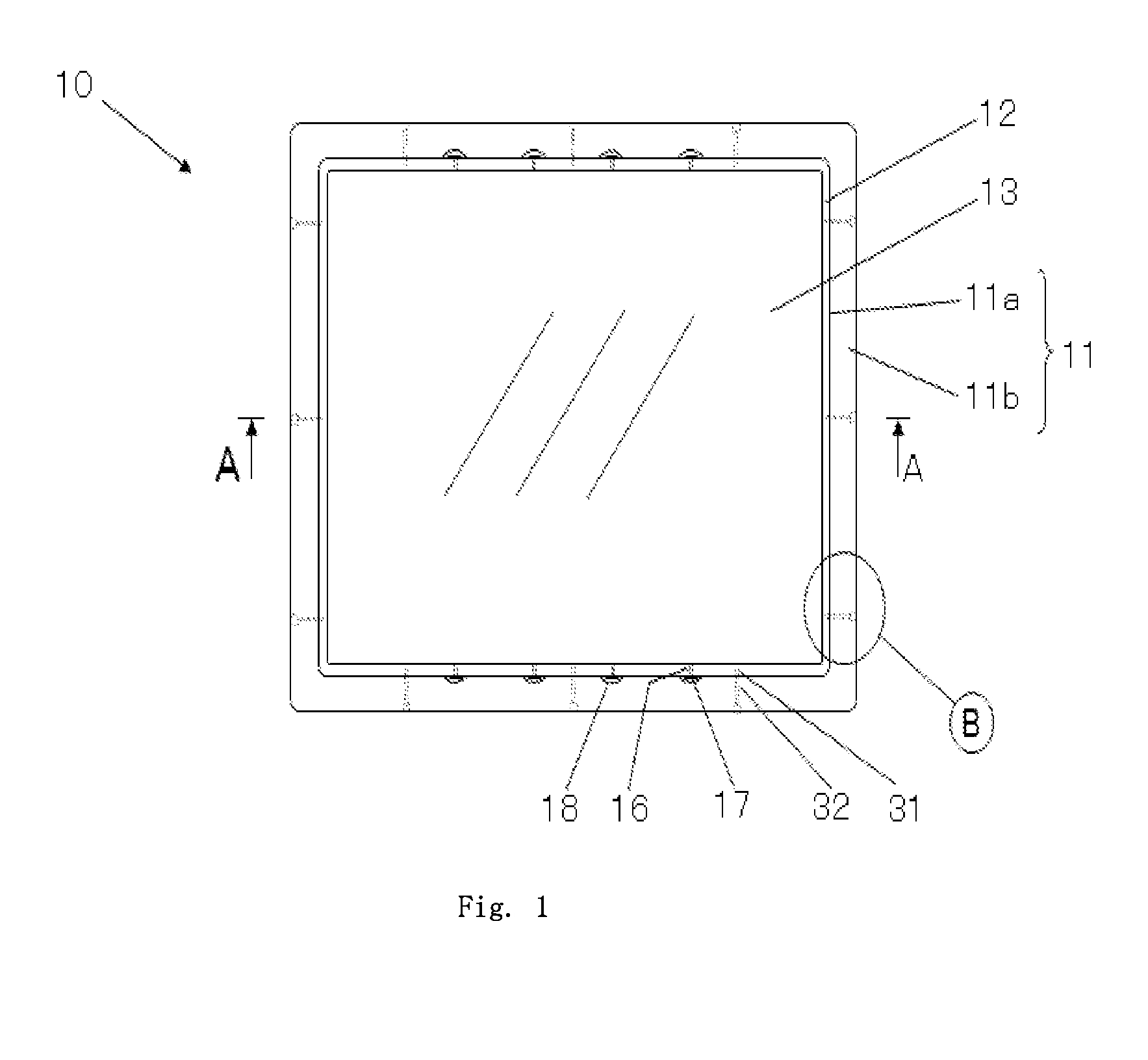
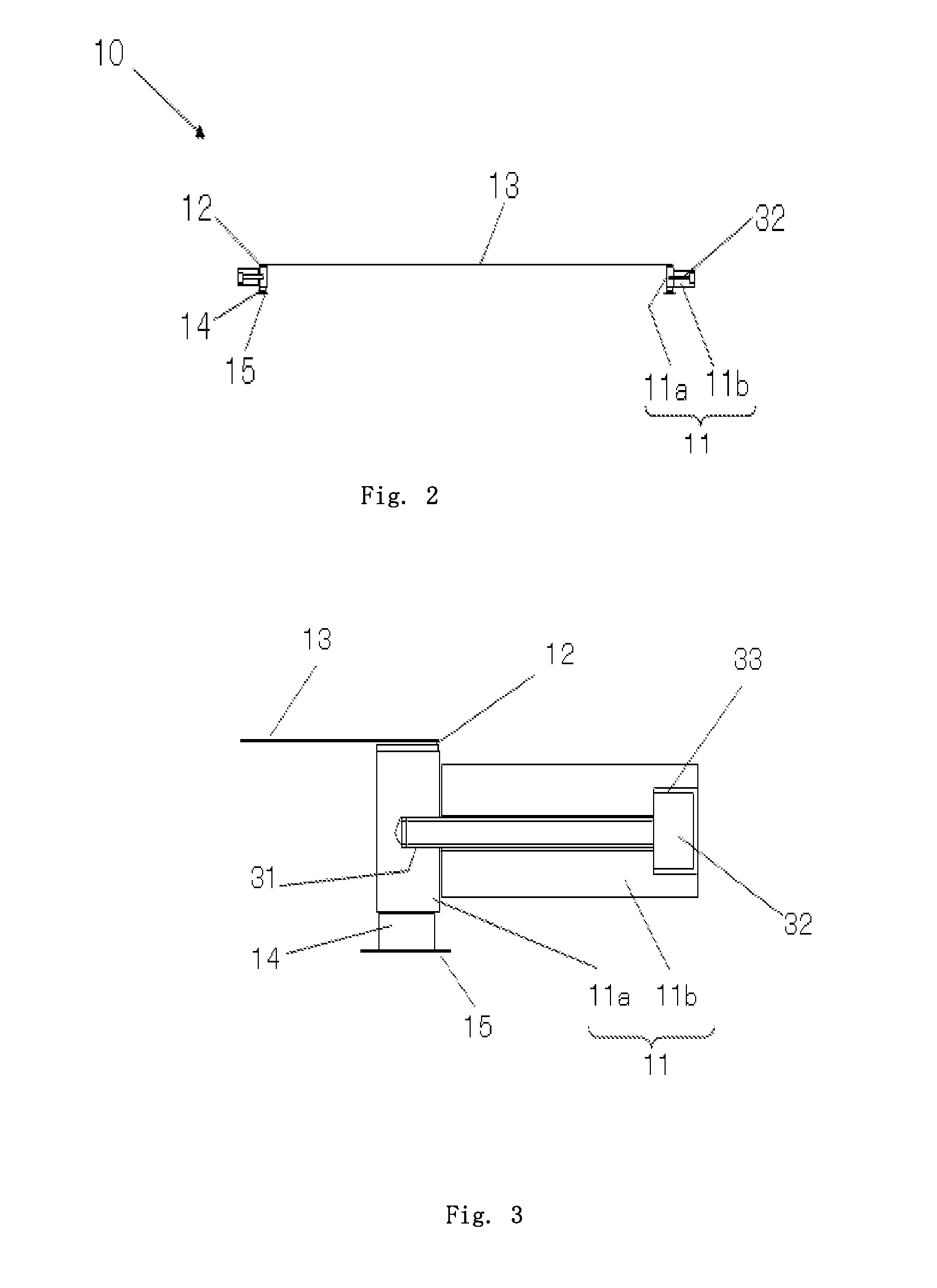
[0042]An inner frame 11a made of an aluminum alloy and having an external dimension of 474 mm×782 mm, an internal dimension of 466 mm×774 mm and a height of 4.9 mm was made by machining and was used to make up a pellicle frame 11 shown in FIGS. 1, 2 and 3, and the surface of the frame 11a was blackened by alumite treatment. Also the outside wall of the inner frame 11a was formed with a non-penetrating female screw 31 and an air vent 16 at positions shown in FIG. 1.

[0043]An outer frame 11b made of an aluminum alloy and having an external dimension of 514 mm×822 mm, an internal dimension of 474 mm×782 mm and a height of 4.0 mm was made by machining, and its surface was blackened by alumite treatment. On this occasion, the dimensional tolerance between the external dimension of the inner frame 11a and the internal dimension of the outer frame 11b at each side bar was set to 0.05-0.1 mm. A counter-bore 33 was made to receive a bolt head in the outer frame 11b at a location corresponding...

example 2

[0050]An inner frame 11a made of a carbon steel and having an external dimension of 904.5 mm×750 mm, an internal dimension of 896.5 mm×742 mm and a height of 5.8 mm was made by machining and was used to make up a pellicle frame 11 shown in FIG. 1, and the surface of the frame 11a was subjected to a black chrome plating treatment. Also the outside wall of the inner frame 11a was formed with a non-penetrating female screw 31 and an air vent 16 at positions shown in FIG. 1.

[0051]Also, an outer frame 11b made of an aluminum alloy and having an external dimension of 924.5 mm×790 mm, an internal dimension of 904.5 mm×750 mm and a height of 5.0 mm was made by machining, and its surface was blackened by alumite treatment. On this occasion, the dimensional tolerance between the external dimension of the inner frame 11a and the internal dimension of the outer frame 11b at each side bar was set to 0.05-0.1 mm. A counter-bore 33 was made to receive a bolt head in the outer frame 11b at a locati...


PUM


Abstract

A pellicle is proposed in which the frame is composed of a detachable double structure of an inner frame and an outer frame, and the pellicle membrane is adhered only to the inner frame and the photomask-agglutination layer is laid only to the inner frame, and the outer frame is removed from the inner frame after the pellicle is agglutinated to the photomask.

Description

[0001]The present non-provisional patent application claims priority, as per Paris Convention, from Japanese Patent Application No. 2012-228582 filed on 2012 Oct. 16, the disclosure of which is hereby incorporated by reference herein in its entirety.FIELD OF THE INVENTION[0002]The present invention relates to a pellicle useful as a dust-fender employed in the scenes of manufacturing semiconductor devices, IC packages, printed circuit boards, liquid crystal display panels, organic EL display panels, etc.BACKGROUND TECHNOLOGY[0003]In manufacturing semiconductor devices such as LSI and super-LSI or in manufacturing a liquid crystal display panel or the like, a pattern is made by irradiating a ultraviolet light to a semiconductor wafer or a glass plate for liquid crystal, but if a dust particle is sticking to a photomask used in this stage, the particle obstructs the light or refracts it, causing deformation of a transferred pattern, short-circuitry, or the like, and thus this phenomeno...

Claims


Application Information

Patent Timeline
IPC IPC(8): G03F1/64
CPCG03F1/64Y10T428/24008G03F1/62H01L21/0274
Inventor SEKIHARA, KAZUTOSHI
Owner SHIN ETSU CHEM CO LTD
Features
  • Generate Ideas
  • Intellectual Property
  • Life Sciences
  • Materials
  • Tech Scout
  • Unparalleled Data Quality
  • Higher Quality Content
  • 60% Fewer Hallucinations
Learn More