
Mining elevator

Active Publication Date: 2014-04-24
DONGNAN ELEVATOR +1
View PDF15 Cites 24 Cited by
  • Summary
  • Abstract
  • Description
  • Claims
  • Application Information

AI Technical Summary

Benefits of technology

The present invention provides a mining elevator with the following technical effects: compact structure, reliable braking capability, low maintenance cost, ride comfort, and high operating efficiency. The elevator uses an explosion-proof traction machine, an explosion-proof control cabinet, and an explosion-proof control box, which allows for safer and reliable use in mines with explosive gases. The elevator employs a flexible guide rail that can guide vertically and restrain transversal deflection, reducing wear and tear on the guide rails and improving safety and reliability. The elevator also introduces a braking rope that replaces the rigid guide rail used in safety clamps, improving braking safety and reliability under emergency situations. Additionally, the elevator has a supporting device for access of a mine car and car arresters for preventing the mine car from moving freely, extending the transportation function of elevator car. The invention also introduces a compensating rope suspender that allows for faster connection of compensating ropes and improves compensating rope reliability. The mining elevator solves problems of high cost and long construction cycle when existing elevators are used for the mining work at multiple-level working faces in mines. It is suitable for use in harsh environments in mines where explosive gases and shaft deformation exist, and achieves reliable braking, low maintenance cost, ride comfort, high operating efficiency, and wide applicability.

Problems solved by technology

However, for the underground mining at multiple-level working faces, in particular for lifting and lowering of materials and workers with the lifting height of less than 400 meters, the use of conventional elevators will lead to high cost and long construction cycle; in addition, when workers are lifted / lowered by means of an elevator, the occupants in the cage are unable to control the lifting / lowering process and are unable to transfer information to the well top or well bottom, and therefore cannot contact with the person at the well top or the well bottom in case that any emergency happens during the transport process; moreover, since the winch has a large structure and low mechanical efficiency, if the winch malfunctions during the operating process, the cage lacks an effective over-speed control; furthermore, lifting / lowering of elevator with cage causes poor ride comfort.
Though existing elevator systems provide better ride comfort, are suitable for working in multiple level working faces, and require low maintenance cost, the traction machine, control cabinet, and control box in the elevator car of existing ordinary industrial elevators can not meet the requirements of the harsh operating environments in mines, because explosive mixed gasses (methane, coal gas, etc.) and corrosive gasses exist in such environments; the rigid guide rails of existing ordinary industrial elevators cannot meet the requirements for lifting in mine wells, because the well shafts are apt to deform under huge side pressure; because the connecting devices of traction ropes employ compression spring and rubber material, which achieve buffering and vibration damping effects, but also may cause unbalanced tension of traction ropes after they are used over a period of time owing to the manufacturing error of traction ropes and the difference of materials; the existing safety clamp system can only be used in rigid guide rails for over-speed runaway safeguard, and there is no safety braking system for elevator cars of non-rigid guide rails up to now; though existing elevator cars can meet the demand for lifting of person and ordinary goods, and accomplish safe, reliable and comfortable lifting, they do not have the loading capability of mobile cars (e.g., mine cars) and therefore cannot be used for lifting in mines, because they do not have supporting device and car arrester.
1) For mining at multiple level working faces in mines, existing elevators have problems of high cost and long construction cycle;
2) The traction and control system of ordinary industrial elevators cannot meet the requirement for use in environments in mines where explosive and corrosive gases exist;
3) The rigid guide rails of existing elevators cannot meet the requirement for use in harsh conditions in mine wells where the shaft is apt to deform;
4) The connecting devices of traction ropes that employ compression spring and rubber material may cause unbalanced tension;
5) There is no safety protection system for elevator car of non-rigid guide rails;
6) There is no composite elevator car system for workers and cars which mine car can enter into and be lifted.

Method used


Image

  • Mining elevator
  • Mining elevator
  • Mining elevator

Examples


Embodiment Construction

[0025]Hereunder the present invention will be detailed in embodiments with reference to the accompanying drawings.

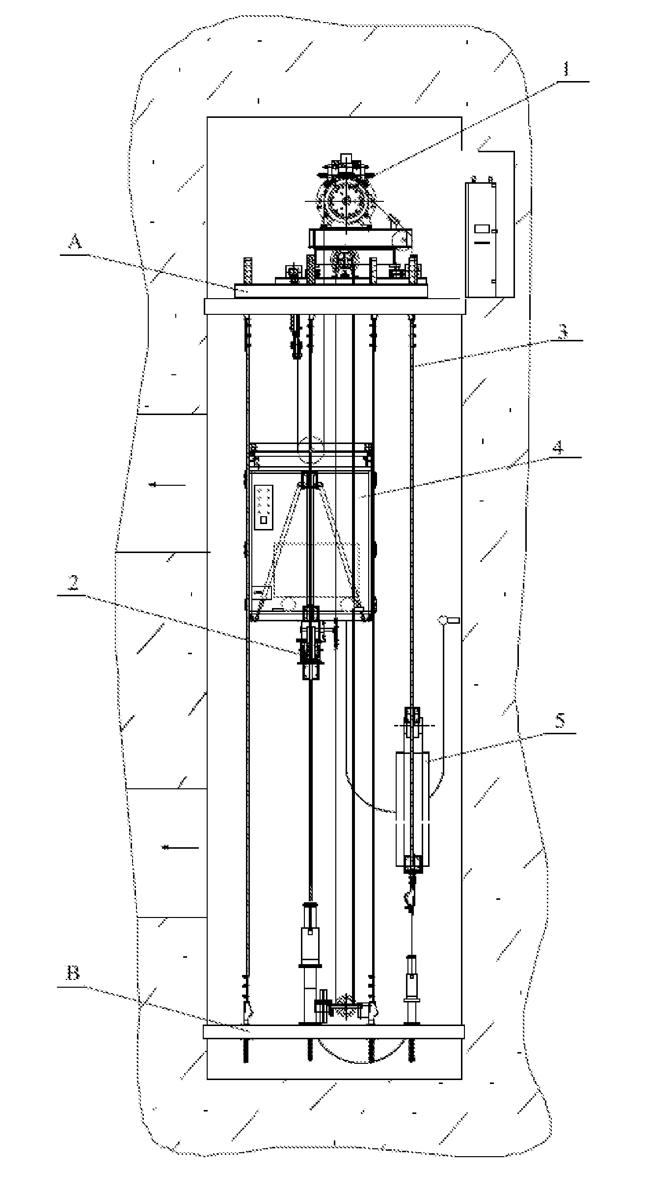
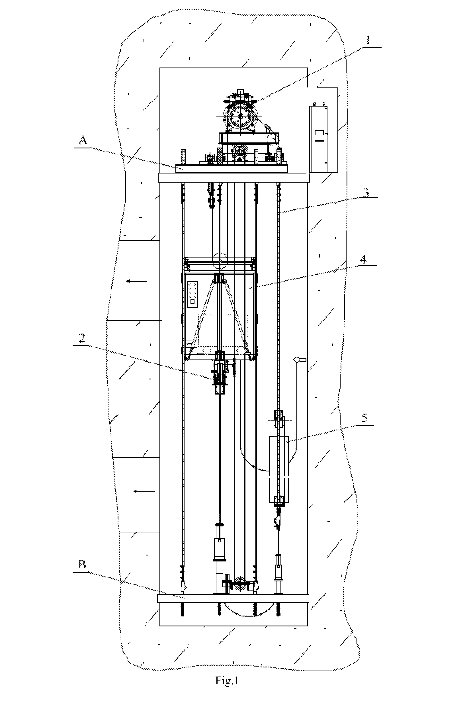
[0026]As shown in FIG. 1, the mining elevator disclosed in the present application comprises an explosion-proof traction system 1, an explosion-proof elevator car protection system 2, a flexible guide rail guiding system 3, a composite elevator car 4, and a counterweight system 5, wherein, the explosion-proof traction system 1 is arranged on an upper platform A on the top at the well top, and the flexible guide rail guiding system 3, composite elevator car 4, and counterweight system 5 are arranged between the upper platform A on the top and a lower platform B in a bottom pit respectively.

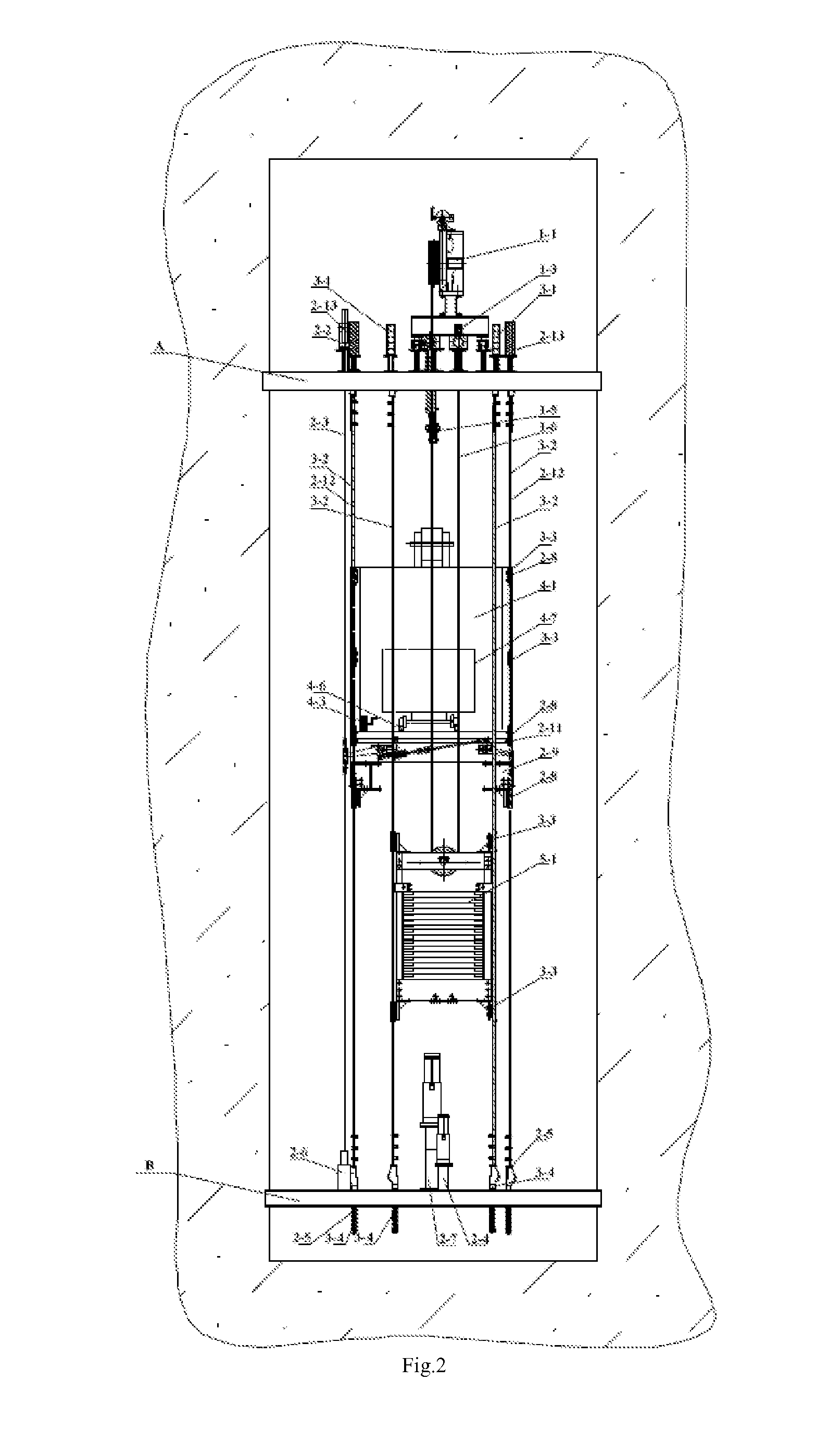
[0027]As shown in FIGS. 2-4, the explosion-proof traction system 1 comprises an explosion-proof traction machine 1-1 connected to an explosion-proof control cabinet 1-2 arranged on the upper platform A, and a traction rope 1-6 wound on the explosion-proof traction machine 1-1, with one ...


PUM


Abstract

A mine elevator is provided having an anti-explosion traction system, an anti-explosion lift car protection system, a flexible guide rail guiding system, a compound lift car, and a counterweight system. The anti-explosion traction system comprises a traction rope tension regulating device, an anti-explosion traction machine, and an anti-explosion control cabinet. The anti-explosion lift car protection system comprises a rope holder, a speed limiter, two hydraulic buffers, a safety clamp, a brake rope, and a brake rope tension buffer device. The flexible guide rail guiding system comprises a steel wire rope guide rail, a guide rail tension device connected to the steel wire rope guide rail and fixed to the an upper platform, a guide rail connection device connected to the steel wire rope guide rail and fixed to a lower platform, and a flexible guide rail guide sleeve fixed to the compound lift car and the counterweight system.

Description

BACKGROUND[0001]1. Technical Field[0002]The present disclosure relates to a mining elevator, which is especially suitable for lifting of materials mined underground and workers in mines.[0003]2. Description of the Related Art[0004]The workers and materials are mainly lifted and lowered by means of elevator and cage during the underground mining process in mines. However, for the underground mining at multiple-level working faces, in particular for lifting and lowering of materials and workers with the lifting height of less than 400 meters, the use of conventional elevators will lead to high cost and long construction cycle; in addition, when workers are lifted / lowered by means of an elevator, the occupants in the cage are unable to control the lifting / lowering process and are unable to transfer information to the well top or well bottom, and therefore cannot contact with the person at the well top or the well bottom in case that any emergency happens during the transport process; m...

Claims


Application Information

Patent Timeline
IPC IPC(8): B66B17/00B66B5/16B66B15/08
CPCB66B17/00B66B5/16B66B15/08B66B7/02B66B17/04B66B7/08B66B5/24B66B9/00B66B15/00B66B11/08B66B5/04
Inventor ZHU, ZHENCAICAO, GUOHUAQIN, JIANCONGKANG, HONGQIAOCHEN, GUOANWU, RENYUANZHOU, GONGBOLI, WEIMA, YIPINGYANG, JIANRONG
Owner DONGNAN ELEVATOR
Learn More