
Battery control device and battery system

a battery control device and battery technology, applied in battery/fuel cell control arrangement, instrumentation, capacitor propulsion, etc., can solve problems such as overcharge or overdischarge, and achieve accurate charging or discharging power.

Active Publication Date: 2014-04-24
HITACHI AUTOMOTIVE SYST LTD
View PDF2 Cites 56 Cited by
  • Summary
  • Abstract
  • Description
  • Claims
  • Application Information

AI Technical Summary

Benefits of technology

The present invention is a battery control device that can accurately determine the permissible charging or discharging power even if the internal resistance of the single cell changes during its charging or discharging duration time. This is achieved by switching the internal resistance value according to the change, making sure to follow up on the internal resistance variation.

Problems solved by technology

If the storage battery is charged or discharged in excess of the maximum permissible power, it could be overcharged or overdischarged.
In spite of the large maximum permissible power at the high temperature, the use of the storage battery in the high-temperature state promotes its deterioration.

Method used


Image

  • Battery control device and battery system
  • Battery control device and battery system
  • Battery control device and battery system

Examples


first embodiment

Conclusion

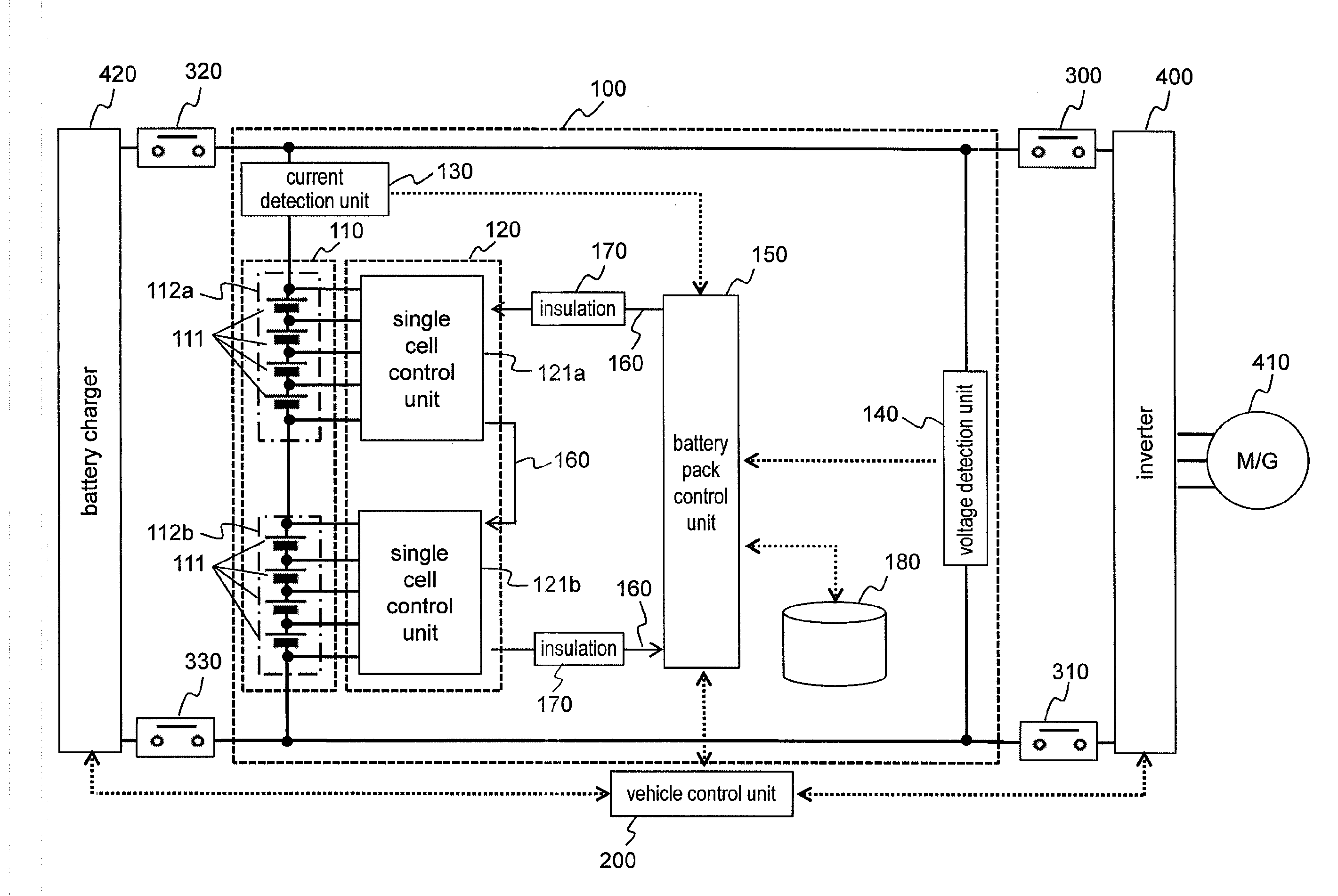
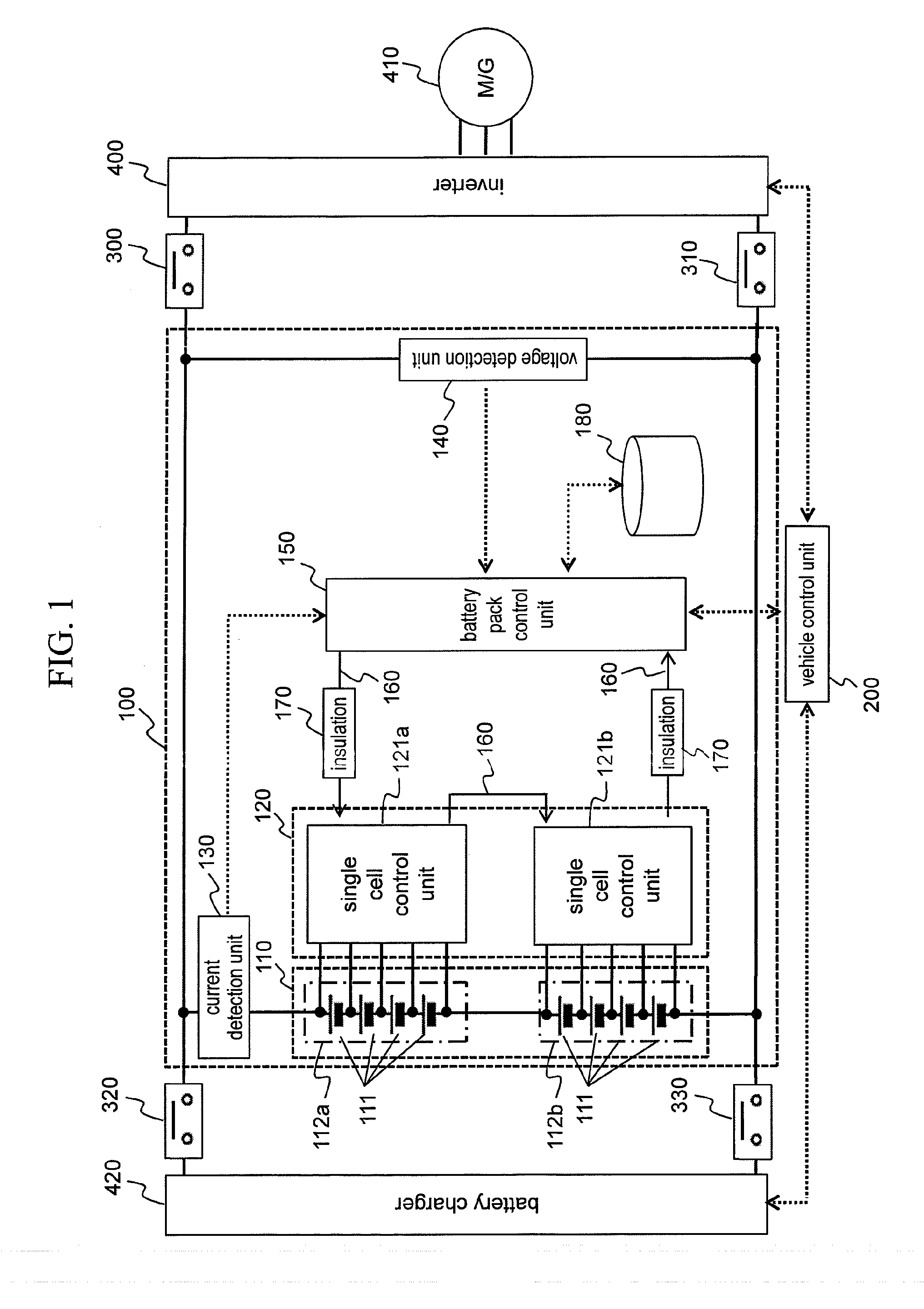
[0072]As described above, the battery system 100 of the first embodiment includes the internal resistance table 182 composed of two-dimensional maps which are provided per charging duration time and which describe the internal resistance values corresponding to the temperature and SOC of the single cells 111. The battery system 100 obtains the internal resistance value of the single cells 111 from the internal resistance table 182 by using the temperature, SOC, and charging duration times of the single cells 111. Based on the internal resistance value thus obtained, the battery system 100 acquires the permissible charging current for the single cells 111. In this manner, the optimal permissible charging current is obtained in accordance with the internal resistance value of the single cells 111 varying with the charging duration time, whereby charging control is implemented.

[0073]For the first embodiment, the operations for charging the single cells 111 were explained abov...

second embodiment

[0074]The first embodiment was explained using examples in which the internal resistance value of the single cells 111 is changed depending on the charging or discharging duration time when the permissible charging or discharging current is to be obtained. Although this method is effective for such forms of operation as electric vehicles that take a relatively long time to charge and discharge, the method may not be mandatory for forms of operation such as hybrid electric vehicles that use batteries over relatively short periods of time.

[0075]The second embodiment is explained below with an example where the battery system 100 operates switchably either in an operation mode in which the system 100 supplies power to an electric vehicle or in an operation mode in which the system 100 feeds power to a hybrid electric vehicle and where the procedure for calculating the permissible charging or discharging current is switched according to operation mode switchover. Since the configuration...

third embodiment

[0082]With the first and the second embodiments above, the permissible charging or discharging current may be calculated by taking the state of health (SOH) of the single cells 111 into consideration. The SOH in this context signifies the rate of increase in internal resistance due to deterioration. The value of the SOH is assumed to be 1 when the single cells 111 are brand-new and become larger as deterioration advances. Explained for the third embodiment of this invention is an operation example in which the SOH is taken into account. Any known method may be used to acquire the SOH of the single cells 111, and thus the method will not be discussed further in conjunction with the third embodiment. It should be noted, however, that the SOH is assumed here to be derived from the rate of increase in internal resistance detected per single cell 111 and applied to calculating the permissible current for each single cell 111.

[0083]FIG. 9 is a chart showing in control blocks the method wh...


PUM


Abstract

An object of the invention is to provide a battery control apparatus capable of accurately obtaining permissible charging or discharging power in keeping with variation of the internal resistance of a battery. The battery control apparatus of this invention includes an internal resistance table in which the internal resistance value of single cells corresponding to the temperature and state of charge thereof are described in association with each of charging or discharging duration time of the single cells. The battery control apparatus calculates a permissible charging current or a permissible discharging current by using the internal resistance value described in the internal resistance table and controls the charging or discharging of the single cells in accordance with the current value thus obtained.

Description

TECHNICAL FIELD[0001]The present invention relates to a technique for controlling a battery.BACKGROUND ART[0002]Electrically powered vehicles are mounted with storage batteries such as lead-acid batteries, nickel metal hydride batteries, and lithium-ion batteries. The power needed by hybrid vehicles or electric cars for traveling is provided by these batteries.[0003]A storage battery mounted on the vehicle is used in a wide temperature range and has maximum permissible power commensurate with the temperature of the storage battery. If the storage battery is charged or discharged in excess of the maximum permissible power, it could be overcharged or overdischarged.[0004]A storage battery generally has small maximum permissible power at a low temperature and large maximum permissible power at a high temperature. In spite of the large maximum permissible power at the high temperature, the use of the storage battery in the high-temperature state promotes its deterioration. Meanwhile, as...

Claims


Application Information

Patent Timeline
Patent Type & Authority Applications(United States)
IPC IPC(8): H02J7/00G01R31/36B60L50/16
CPCG01R31/3606H02J7/007H01M10/441H01M10/482B60L2210/40B60L2240/545B60L2240/547B60L2240/549Y02T90/14Y02T10/70H02J7/14Y02T10/7072B60L53/14B60L50/40B60L50/16B60L50/51B60L58/16B60L58/13B60L58/21G01R31/389G01R31/396H02J2310/46H02J7/007194Y02T10/72Y02E60/10H02J7/04H02J7/00714G01R31/382Y02T90/12
Inventor OHKAWA, KEIICHIRONAKAO, RYOUHEIKAWAHARA, YOUHEI
Owner HITACHI AUTOMOTIVE SYST LTD
Learn More