Method and apparatus for optimization of a pulse sequence for a magnetic resonance system

a magnetic resonance system and pulse sequence technology, applied in the direction of reradiation, measurement using nmr, instruments, etc., can solve the problems of high hardware requirements, high power consumption, and steep edges, and achieve the effect of shortening the pulse duration, increasing the patient's sar load, and reducing the number of steep edges

Active Publication Date: 2014-04-24
SIEMENS HEALTHCARE GMBH
View PDF2 Cites 11 Cited by
  • Summary
  • Abstract
  • Description
  • Claims
  • Application Information

AI Technical Summary

Benefits of technology

[0013]in accordance with the invention, a pulse sequence whose parameters have been determined in a known manner is an input variable of the method to optimize a pulse sequence for a magnetic resonance system. The pulse sequence or its parameters result(s) from the imaging task to be achieved. The pulse sequence includes at least one refocusing pulse, a slice-selection gradient pulse and a gradient spoiler pulse. The time length, amplitude and edge steepness of this gradient spoiler are respectively determined. The gradient spoiler pulse or gradient spoiler lies chronologically before or after the slice-selection gradient pulse. The pulse sequence is optimized for a noise reduction. The pulse duration of the refocusing pulse is thereby shortened. A refocusing pulse is also called a rephasing pulse and serves to bundle again the divergent phases of the signals radiated from the excited nuclei.
[0034]The shortening of the refocusing pulse or refocusing pulses allows more time not only for the gradient spoiler pulses, but also for the readout spoiler pulses and the phase coding pulses. In addition to the modification of the gradient spoiler pulses (and possibly the readout spoiler pulse) to keep the total spoiler moment constant, it is therefore possible to likewise reduce the edge steepness of the readout spoiler pulse or, respectively, the readout spoiler pulses and / or the phase coding pulses. It should be noted again that edge steepness is frequently also designated as slew rate. Both the readout spoiler pulses an the phase coding pulses contribute to the noise development in a magnetic resonance system. If these edges are likewise designed to be flatter, this therefore leads to an additional noise reduction. This can be in a range from approximately 1 to approximately 10 dBA.

Problems solved by technology

In particular, a high edge steepness contributes to the noise exposure.
In addition, steep edges lead to a higher power consumption and additionally place higher demands on the hardware.
The rapidly changing gradient fields lead to distortions and oscillations in the gradient coils and to the transmission of these energies to the apparatus housing.
A disadvantage in the selection of such a quiet gradient mode is that not only is the measurement time made longer overall, but also the image quality (for example the contrast and / or the resolution) is reduced.
Therefore, not much time is provided for the execution of the spoilers.
This means that the spoiler amplitudes must necessarily be high to achieve a defined spoiler moment, which leads to high edge steepness of the spoiler pulses directly.
A large part of the noise in MRT examinations, particularly given the use of SE or TSE sequences, therefore results from the spoiler pulses.

Method used


Image

  • Method and apparatus for optimization of a pulse sequence for a magnetic resonance system
  • Method and apparatus for optimization of a pulse sequence for a magnetic resonance system
  • Method and apparatus for optimization of a pulse sequence for a magnetic resonance system

Examples


Embodiment Construction

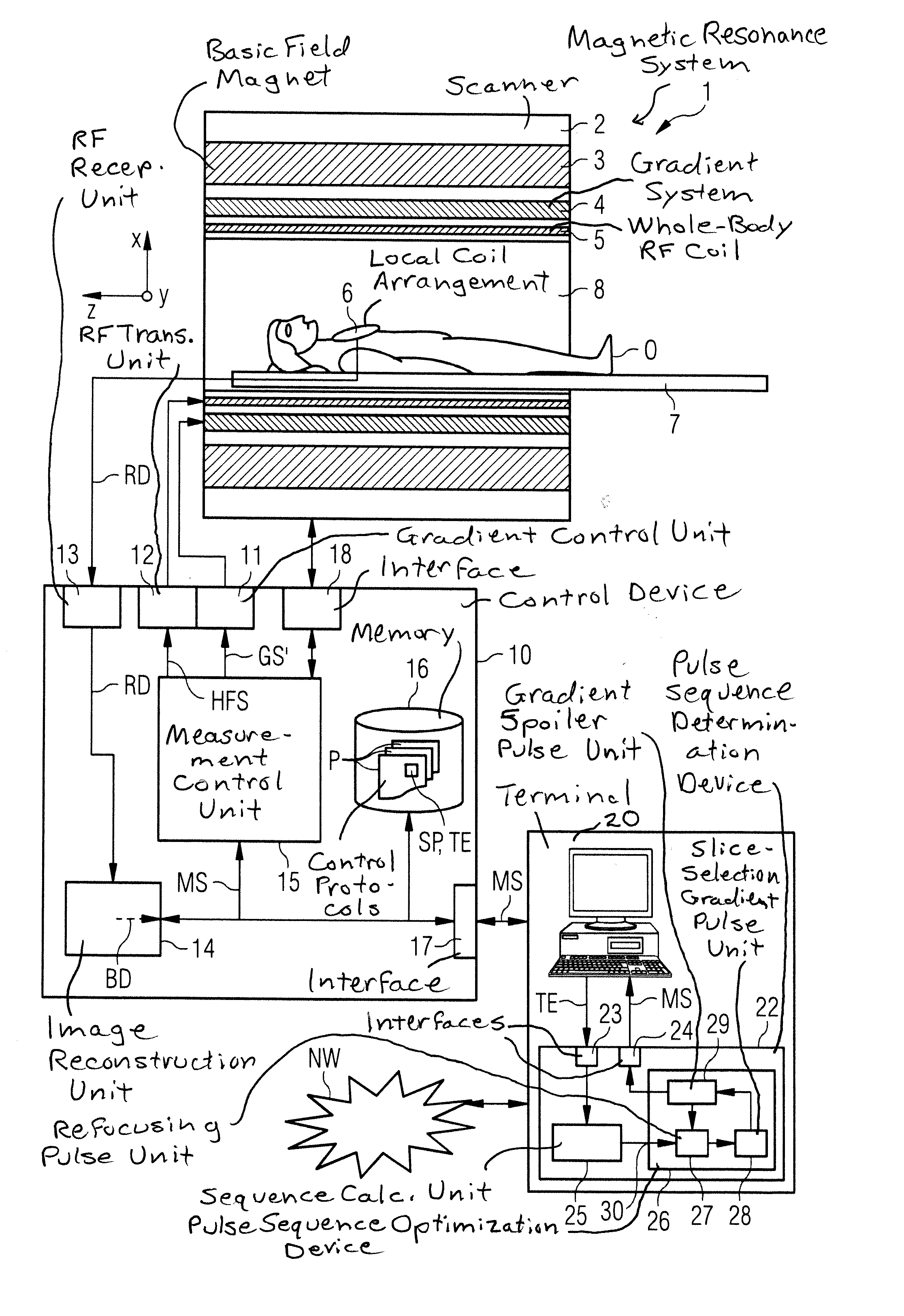
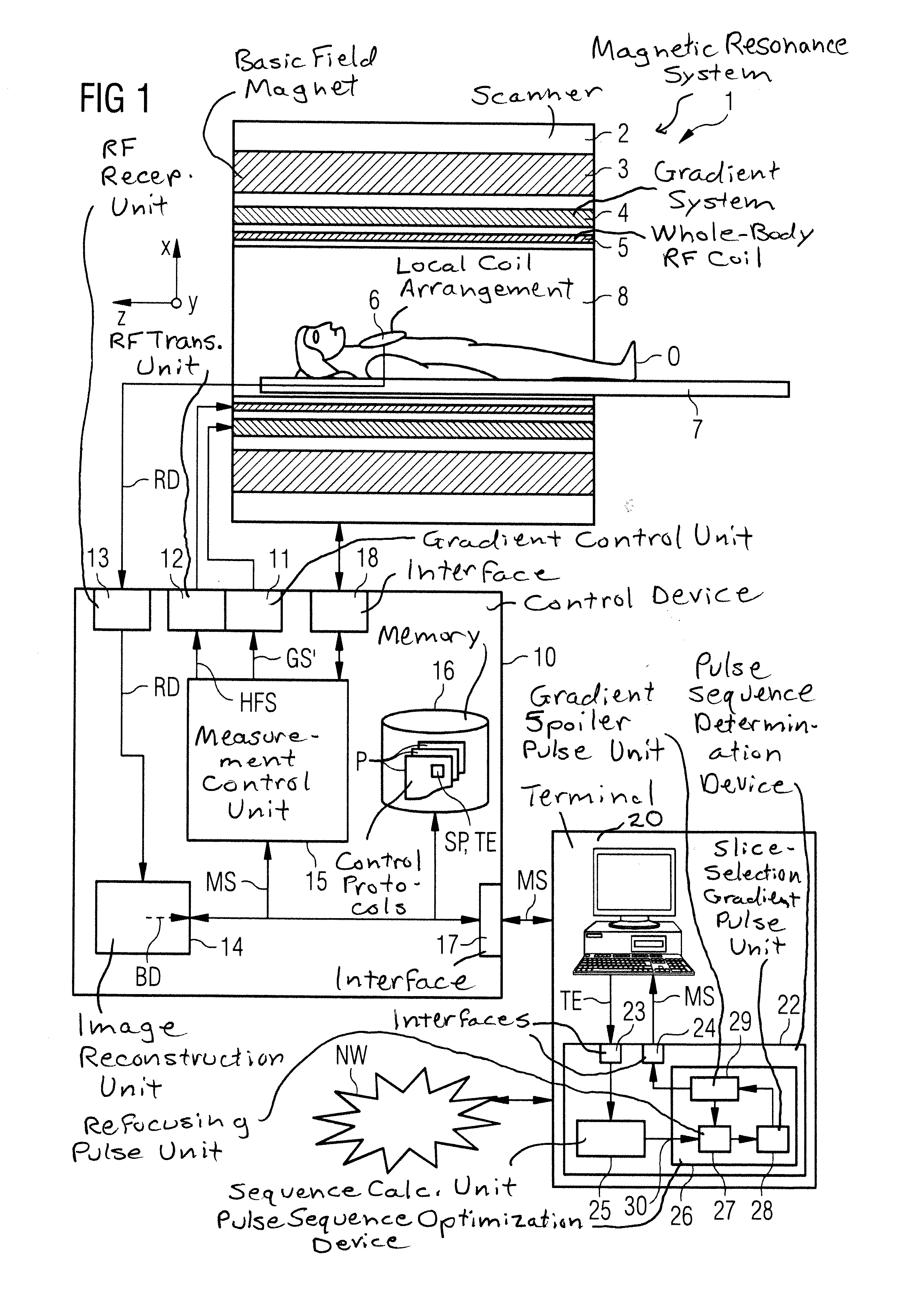
[0045]A magnetic resonance system 1 according to the invention is schematically shown in FIG. 1. It includes the actual magnetic resonance scanner (data acquisition unit) 2 with an examination space or patient tunnel located therein. A bed 7 can be driven into this patient tunnel 8, such that a patient O or examination subject on said bed 7 can be supported at a defined position within the magnetic resonance scanner 2 relative to the magnet system and radio-frequency system arranged therein during an examination, or can be moved between different positions during a measurement.

[0046]Basic components of the magnetic resonance scanner are a basic field magnet 3, a gradient system 4 with magnetic field gradient coils to generate magnetic field gradients in the x-, y- and z-directions, and a whole-body radio-frequency coil 5. The magnetic field gradient coils can be controlled independently of one another in the x-, y- and z-direction so that gradients can be applied in arbitrary spatia...


PUM


Abstract

A method and a pulse sequence optimization device to optimize a pulse sequence for a magnetic resonance system, wherein the pulse sequence includes at least one refocusing pulse, one slice selection gradient pulse, and one gradient spoiler pulse. The pulse duration of the refocusing pulse is shortened, and the pulse duration of the slice selection gradient pulse is adapted to the shortened pulse duration of the refocusing pulse. The amplitude of the slice selection gradient pulse is increased so that the same slice thickness is selected as before the shortening of the pulse duration of the refocusing pulse. The pulse shape of the gradient spoiler pulse is adapted without changing a total spoiler moment, and an optimally shortened pulse duration of the refocusing pulse is achieved when, with the adaptation of the pulse shape of the gradient spoiler pulse, the maximum amplitude of the gradient spoiler pulse equals the amplitude of the slice selection gradient pulse, and an edge steepness of the gradient spoiler pulse is minimized.

Description

BACKGROUND OF THE INVENTION[0001]1. Field of the Invention[0002]The present invention concerns a method to optimize a magnetic resonance pulse sequence that includes a slice-selection gradient pulse and a gradient spoiler pulse, for operating a magnetic resonance system. Moreover, the invention concerns a method to operate a magnetic resonance system using such an optimized pulse sequence, and a pulse sequence optimization device for a magnetic resonance system in order to implement this method.[0003]2. Description of the Prior Art[0004]In a magnetic resonance system (also called a magnetic resonance tomography system), the body to be examined is typically exposed to a relatively high basic magnetic field (for example of 1, 5, 3 or 7 Tesla) with the use of a basic field magnet system. A magnetic field gradient is additionally applied by a gradient system. Radio-frequency excitation signals (RF signals) are then emitted by a radio-frequency transmission system by means of suitable an...

Claims


Application Information

Patent Timeline
Patent Type & Authority Applications(United States)
IPC IPC(8): G01R33/54
CPCG01R33/543G01R33/3854G01R33/4833G01R33/5617
Inventor GRODZKI, DAVIDNITTKA, MATHIAS
Owner SIEMENS HEALTHCARE GMBH
Why Eureka
Try Eureka