Agricultural harvesting machine

Active Publication Date: 2014-04-24
CLAAS SELBSTFAHRENDE ERNTEMASCHINEN GMBH
View PDF7 Cites 8 Cited by
  • Summary
  • Abstract
  • Description
  • Claims
  • Application Information

AI Technical Summary

Benefits of technology

This patent describes a system for measuring the position of a machine's transfer device. The system includes a detection unit and an evaluation unit that are connected through an optical waveguide. By installing the evaluation unit in the driver's cab or maintenance space of the machine, the detection unit remains connected even when the transfer device is removed for maintenance or assembly. This eliminates the need to separate the optical waveguide connection during deinstallation, making the evaluation unit easy to reinstall and use. The technical effect of this system is that it provides accurate position measurement without the need for additional wiring or complicated setup procedures.

Problems solved by technology

For example, the sensors required for detection of the infrared light are exposed to strong vibrations and accelerations during operation, which are caused by crop flowing past and / or by operation-induced machine vibrations and accelerations that are transferred to the transfer device.
During travel across uneven terrain in particular, vibrations have a particularly strong effect on the transfer device due to the lever effect (with increasing distance from the machine) and, in the extreme case, can be audibly perceived as impacts.
The stability of the sensitive sensors is therefore limited.
Also, considerable installation space is required to house the sensors, which can be provided on the outer wall of the transfer device only with the compromise of non-optimal positioning.
Additionally, the design of the measurement device increases the risk of theft since the measurement device is attractive to thieves due to the high value and easy removability thereof.

Method used


Image

  • Agricultural harvesting machine
  • Agricultural harvesting machine
  • Agricultural harvesting machine

Examples


Embodiment Construction

[0030]The following is a detailed description of example embodiments of the invention depicted in the accompanying drawings. The example embodiments are presented in such detail as to clearly communicate the invention and are designed to make such embodiments obvious to a person of ordinary skill in the art. However, the amount of detail offered is not intended to limit the anticipated variations of embodiments; on the contrary, the intention is to cover all modifications, equivalents, and alternatives falling within the spirit and scope of the present invention, as defined by the appended claims.

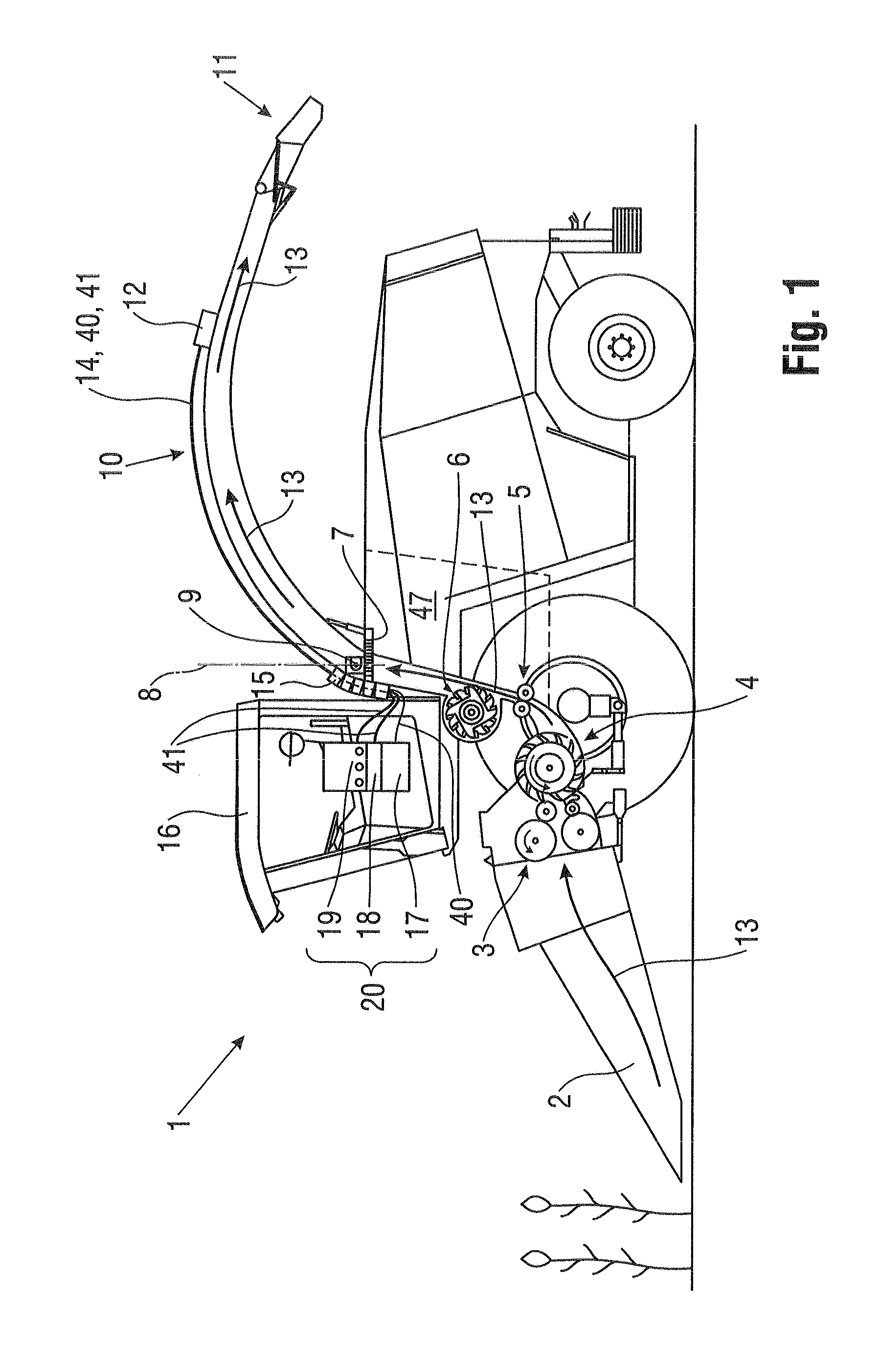
[0031]FIG. 1 shows a schematic side view of a harvesting machine according to the invention, which is a self-propelled forage harvester 1. The forage harvester 1 is equipped with front and rear wheels for harvesting travel over a field and is driven by an engine unit. During harvesting operation, the forage harvester 1 cuts the plant crop (shown at the left in the image) from the field usin...


PUM


Abstract

An agricultural harvesting machine has a measurement device for investigating a crop flow conveyed through the harvesting machine. The measurement device includes at least one optical detection unit disposed at the crop flow for detecting light reflected by the crop and an evaluation unit for evaluating the spectrum of the detected light in order to derive properties of the crop. The evaluation unit is disposed at a position of the harvesting machine that is decoupled from mechanical loading by the crop flow to the greatest extent possible and is connected to the detection unit by way of at least one optical waveguide.

Description

CROSS-REFERENCE TO A RELATED APPLICATION[0001]The invention described and claimed hereinbelow is also described in German Patent Application DE 10 2011 054841.6 filed on Oct. 27, 2011. This German Patent Application, subject matter of which is incorporated herein by reference, provides the basis for a claim of priority of invention under 35 U.S.C. 119(a)-(d).BACKGROUND OF THE INVENTION[0002]The invention relates broadly to an agricultural harvesting machine with a measurement device for investigating a crop flow that includes an optical detection unit for detecting light reflected by the crop and an evaluation unit that evaluates the spectrum of the detected light in order to derive properties of the crop (13) therefrom.[0003]As is known, agricultural harvesting machines convey and process crop and, for many and various reasons, it is interesting to investigate crop conveyed through the machine during a harvesting operation with respect to the properties thereof, such as moisture an...

Claims


Application Information

Patent Timeline
IPC IPC(8): G01N21/55
CPCG01N21/55G01N21/274G01N21/276G01N21/359G01N21/85G01N2021/157G01N2021/8592A01D43/085G01N21/3554G01N21/3563G01N21/27
Inventor CLAUSSEN, FRANK
Owner CLAAS SELBSTFAHRENDE ERNTEMASCHINEN GMBH
Why Eureka
Try Eureka