Connector terminal preparation method

a technology of connecting terminals and terminals, which is applied in the field of electrical signal connectors, can solve the problems of reducing the speed of metal ions deposition on the surface of the metal socket, affecting the performance of electrical connectors, and affecting the use of electrical connectors, so as to facilitate the rapid dissipation of released gases, improve the conductivity and heat resistance of the component parts, and improve the effect of signal transmission efficiency and stability

Inactive Publication Date: 2014-05-01
HSU PO KAI
View PDF15 Cites 2 Cited by
  • Summary
  • Abstract
  • Description
  • Claims
  • Application Information

AI Technical Summary

Benefits of technology

[0008]The present invention has been accomplished under the circumstances in view. It is therefore the main object of the present invention to provide a connector terminal preparation method, which enhances the conductivity, heat resistance and anti-wear and anti-rust properties of the component parts thus made so that the finished connector terminal can provide a high level of signal transmission efficiency and stability.
[0009]To achieve this and other objects of the present invention, a connector terminal preparation method comprises the step of preparing a metal socket comprising a base and a cylindrical body extended from one side of the base and defining with the base an accommodation chamber, and then making a through hole on the base of the metal socket and then dipping the metal socket in an electrolyte solution containing dissolved metal salts and ions in an electroplating machine and applying a direct current to the electrolyte solution for enabling the direct current to go through the through hole and to move evenly over inner and outer surfaces of the base and the cylindrical body of the metal socket so that dissolved metal ions in the electrolyte solution are reduced and deposited onto the metal socket to form a metal coating layer on the inner and outer surfaces of the base and cylindrical body of the metal socket, and the step of removing the metal socket from the electroplating machine and then employing a mechanical processing process to deform the base of the metal socket and to have the through hole of the metal socket be fully enclosed. When depositing the metal coating layer on the inner and outer surfaces of the base and cylindrical body of the metal socket, the structural design of the through hole enables the applied electric current to be evenly distributed over the inner and outer surfaces of the metal socket and facilitates quick dissipation of released gases during electroplating. Thus, the finished metal socket has the characteristic of low resistivity (high conductivity), enhancing signal transmission efficiency and stability.

Problems solved by technology

Further, electrical connectors are intensively used to connect electronic devices to a circuit board.
However, as the metal socket of a pogo pin is a blind hole structure, gases (hydrogen and etc.) released during electroplating may be accumulated in the blind hole of the metal socket, causing cracks in the metal coating layer, or affecting even distribution of electric current to lower the speed of the deposition of metal ions on the surface of the metal socket.
Due to low current efficiency (the ratio of the amount of electricity, in coulombs, theoretically required to yield a given quantity of material in an electrochemical process, to the amount actually consumed), it takes much electroplating time to reach the desired coating thickness.
Because of slow deposition rate, it is difficult to coat the desired metal coating layer on the inner surface of the metal socket.
In consequence, the manufacturing cost of the metal socket is high.

Method used


Image

  • Connector terminal preparation method
  • Connector terminal preparation method
  • Connector terminal preparation method

Examples


Embodiment Construction

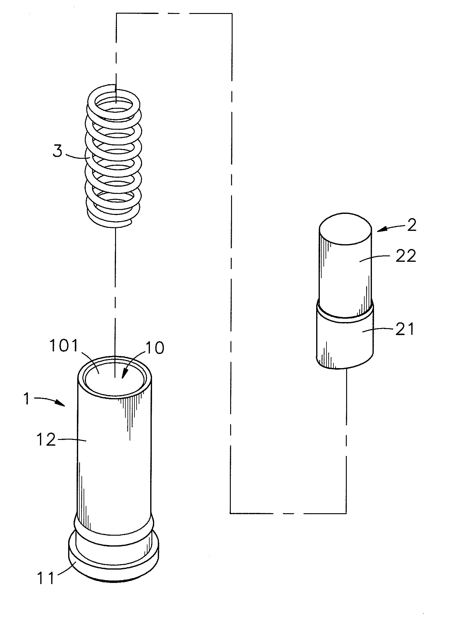
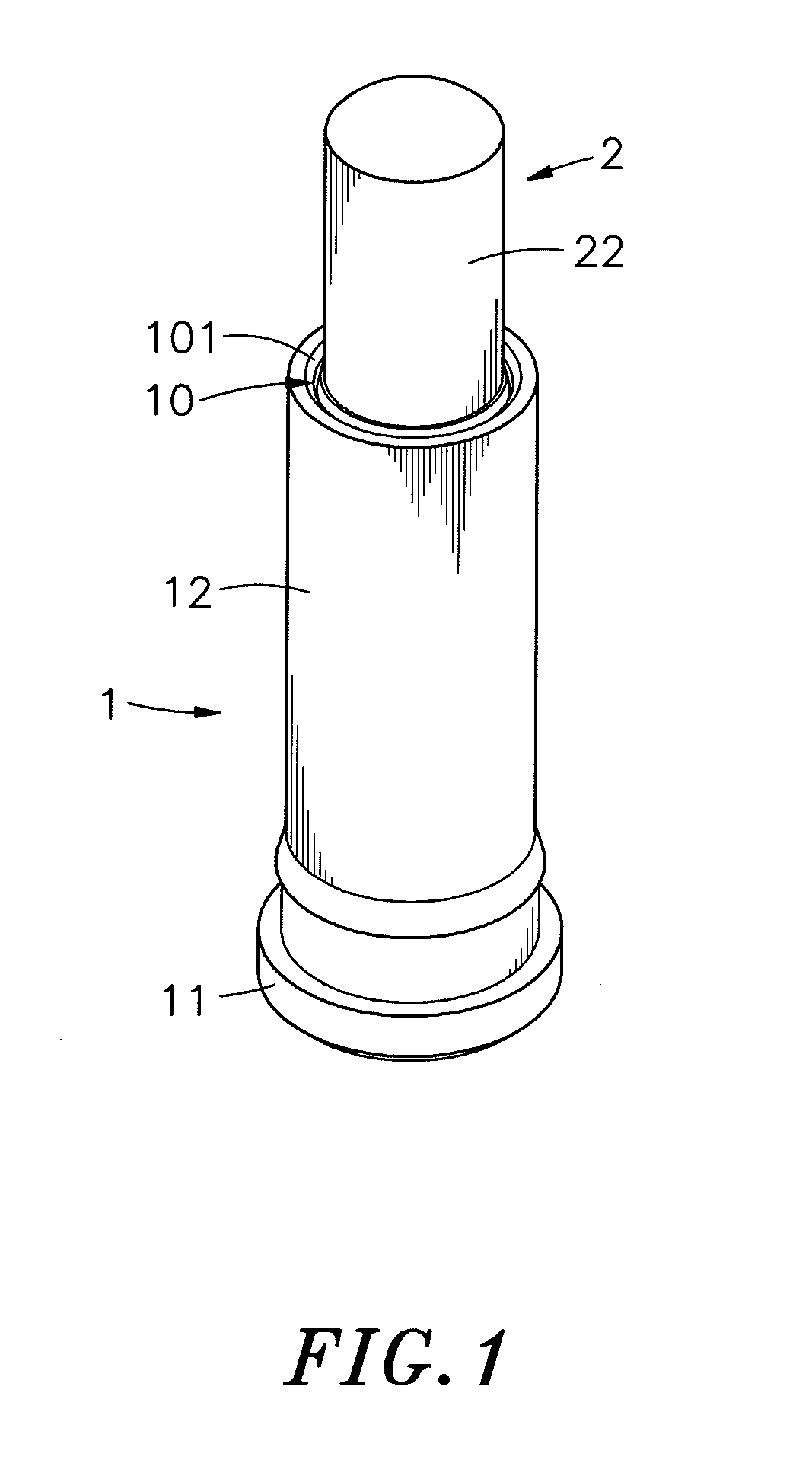
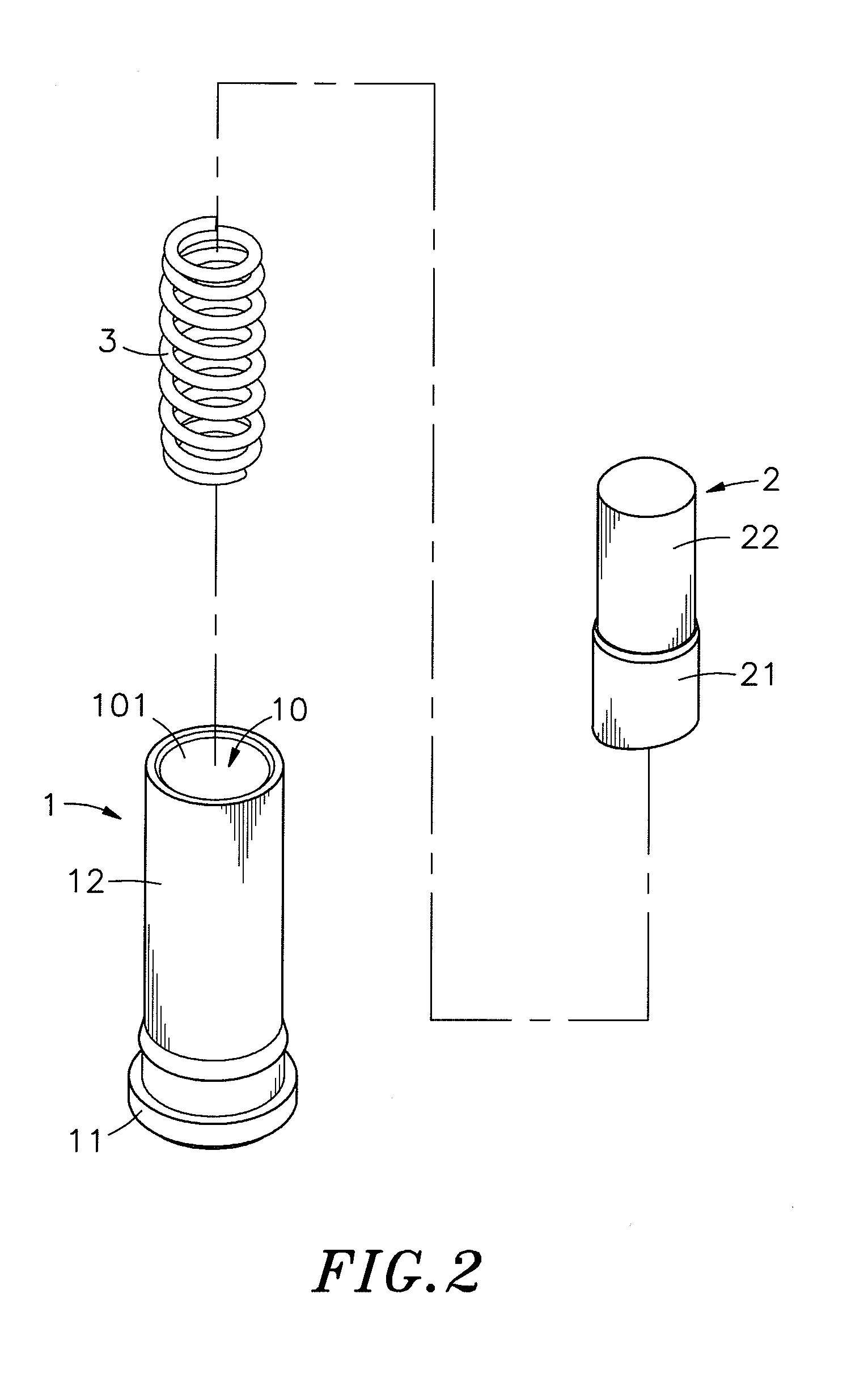
[0022]Referring to FIGS. 1-3, a connector terminal in accordance with the present invention is shown. The connector terminal comprises a metal socket 1, a probe head 2, and an elastic member 3 set between the metal socket 1 and the probe head 2.

[0023]The metal socket 1 comprises a base 11, a cylindrical body 12 perpendicularly extended from one side of the base 11, an accommodation chamber 10 surrounded by the base 11 and the cylindrical body 12 for accommodating the probe head 2 and the elastic member 3, and an opening 101 located on one end, namely, the top end of the cylindrical body 12 remote from the base 11 and disposed in communication with the accommodation chamber 10.

[0024]The probe head 2 is shaped like a stepped cylinder, comprising a lower stoppage portion 21 having a relatively larger diameter and accommodated in the accommodation chamber 10, and an upper contact portion 22 having a relatively smaller diameter and extended from the lower stoppage portion 21 out of the m...


PUM

PropertyMeasurementUnit
diameteraaaaaaaaaa
conductivityaaaaaaaaaa
heat resistanceaaaaaaaaaa

Abstract

A connector terminal preparation method includes the step of preparing a metal socket having a base and a cylindrical body extended from the base and then making a through hole on the base in communication with the inside of the cylindrical body and then electroplating a metal coating layer on the inner and outer surfaces of the base and cylindrical body of the metal socket, and the step of employing a mechanical processing process to deform the base of the metal socket and to have the through hole of the metal socket be fully enclosed.

Description

BACKGROUND OF THE INVENTION[0001]1. Field of the Invention[0002]The present invention relates to electrical signal connectors and more particularly to a connector terminal preparation method, which enhances the conductivity, heat resistance and anti-wear and anti-rust properties of the component parts thus made so that the finished connector terminal can provide a high level of signal transmission efficiency and stability.[0003]2. Description of the Related Art[0004]With the rapid development of electronic technology and multimedia revolution, cell phone, smart phone, GPS navigation device, PDA and many other mobile electronics are created and widely used in different fields. It is now the market tendency to create mobile devices having light, thin, short and small characteristics. In consequence, electronic components for installation in a circuit board for mobile device must be made smaller, more precise and stronger than ever before.[0005]Further, electrical connectors are intens...

Claims


Application Information

Patent Timeline
Patent Type & Authority Applications(United States)
IPC IPC(8): H01R43/16
CPCH01R43/16H01R13/03C25D7/04C25D5/48H01R13/187Y10T29/49204
Inventor HSU, PO-KAI
Owner HSU PO KAI
Why Eureka
Try Eureka