
Drive train, in particular vehicle drive train

a technology for driving trains and vehicles, applied in the field of driving trains, can solve the problems of negative consequences on the overall efficiency of exhaust-gas energy recovery, flow losses, etc., and achieve the effect of increasing the overall efficiency of the turbocharger—turbo compound system and reducing flow losses

Inactive Publication Date: 2014-05-01
VOITH PATENT GMBH
View PDF0 Cites 13 Cited by
  • Summary
  • Abstract
  • Description
  • Claims
  • Application Information

AI Technical Summary

Benefits of technology

The present invention provides a drive train with reduced disadvantages and improved efficiency. By integrating a turbocharger and a turbocompound system, the available space is better utilized and maintenance requirements are reduced. The two systems can be lubricated with the same oil supply, and a short flow guide reduces flow losses and increases efficiency. The two turbines can be arranged in a two-stage compression configuration, and a reverse configuration can also improve efficiency. The system includes an exhaust-gas manifold and a fresh-air manifold to guide the flow of exhaust gas and fresh air, respectively. These design features reduce costs and improve overall efficiency.

Problems solved by technology

This requires, however, flow losses and has negative consequences on the overall efficiency of the exhaust-gas energy recovery.
In addition to the non optimum use of the construction space, a separate lubricant supply is necessary for the turbo machines further to the different positions of installation.
These disadvantages also crop up if, for instance, a drive train is arranged with, instead of the turbo compound system, at least one additional fresh-air compressor and / or exhaust-gas turbine.

Method used


Image

  • Drive train, in particular vehicle drive train
  • Drive train, in particular vehicle drive train
  • Drive train, in particular vehicle drive train

Examples


Embodiment Construction

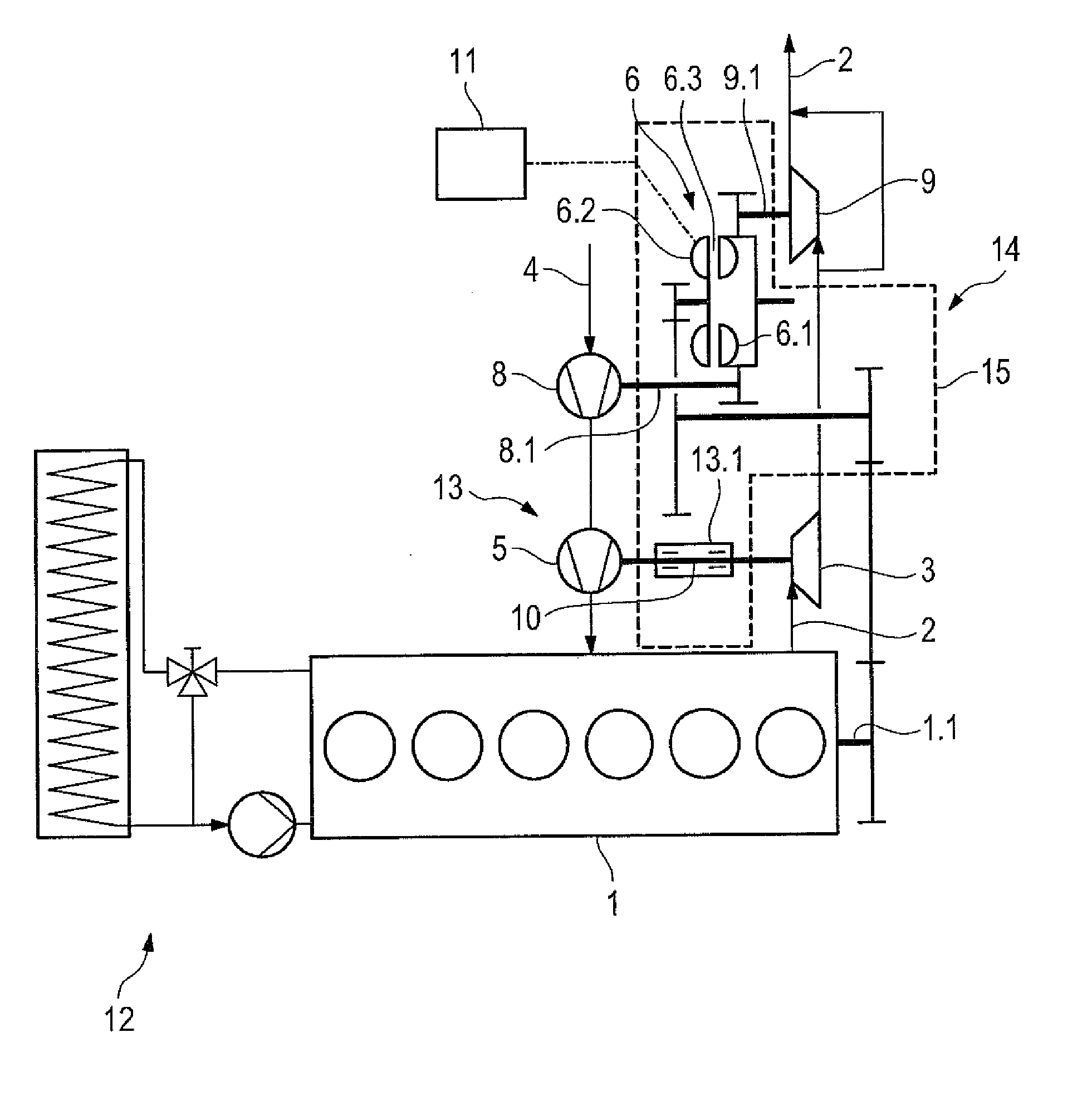
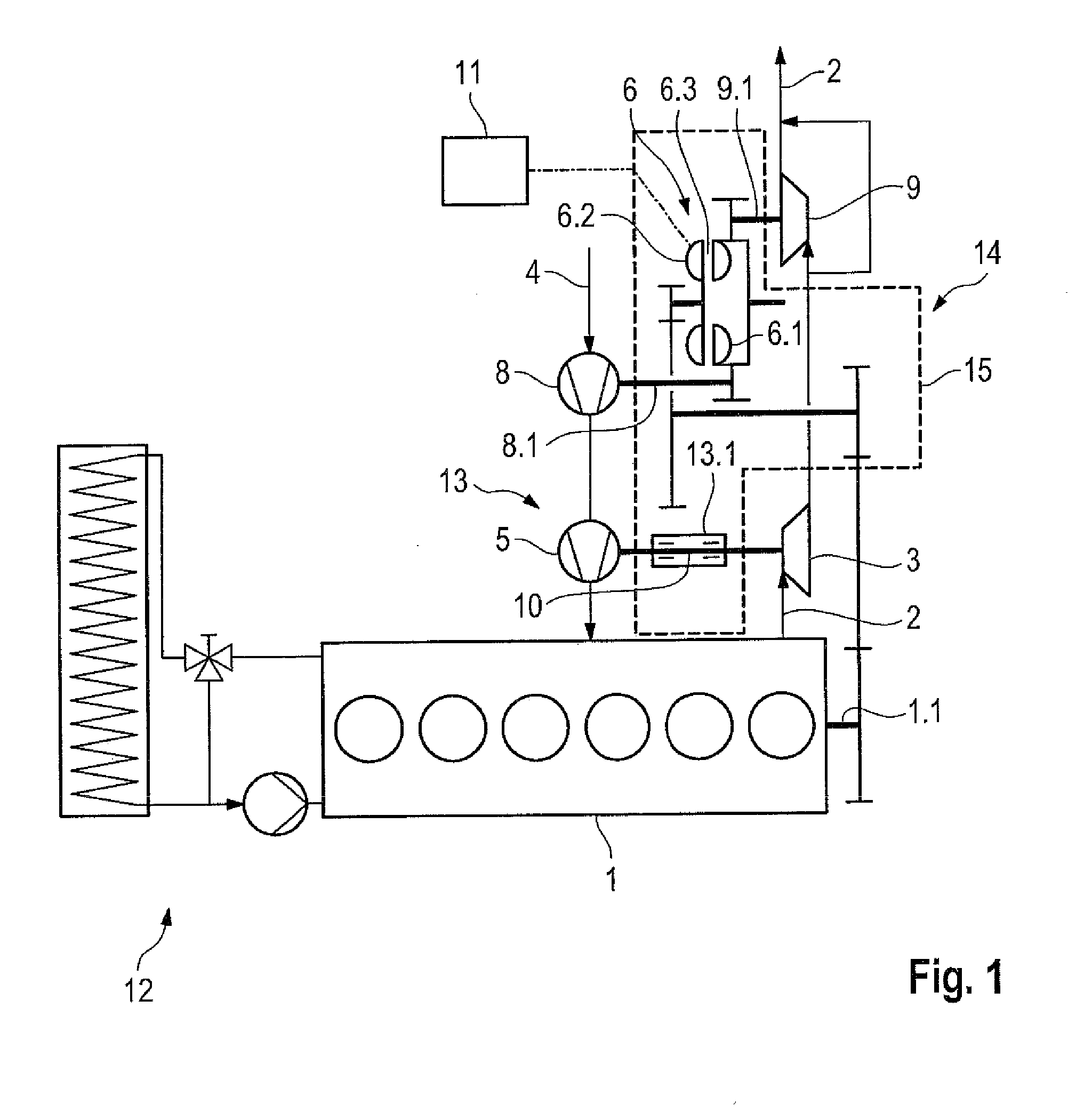
[0035]FIG. 4a shows a drive train of the invention according to one embodiment of the invention, comprising an internal combustion engine 1, such as a diesel engine, having an output shaft 1.1 which can be, for instance, a crankshaft of the internal combustion engine 1. The internal combustion engine 1 is cooled by means of a cooling circuit 12, as shown in FIG. 1. The internal combustion engine 1 generates an exhaust-gas flow 2. Two turbines, namely a first exhaust-gas turbine 3 of a turbocharger 13 and a second turbine, here designated as power turbine 9, are arranged in a row relative to one another and are subjected to exhaust gas from the exhaust-gas flow 2 so that they convert exhaust-gas energy into drive power.

[0036]To do so, the power turbine 9 is arranged in the flow direction of the exhaust gas behind the first exhaust-gas turbine 3 in the exhaust-gas flow 2. The first fresh-air compressor 5 is connected via a common shaft, here a first turbine shaft 10, to the first exha...


PUM


Abstract

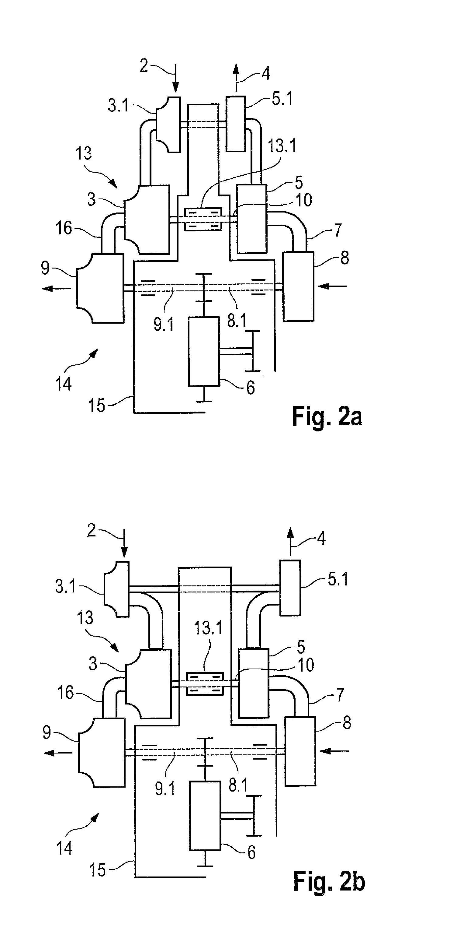
A drive train having an internal combustion engine which includes an output shaft feeding drive power into the drive train. A first turbo charger includes a first exhaust-gas turbine arranged in an exhaust-gas flow and mounted rotatably in a turbine housing that drives a first fresh-air compressor via a first turbine shaft. A turbo-compound system includes a power turbine arranged in the exhaust-gas flow and can be drive connected via a power turbine shaft to the output shaft, with the power turbine shaft mounted rotatably in a power turbine housing and extending parallel to the turbine shaft. The turbine housing and power turbine housing can be supported in or on or integrated into a transmission housing. The first turbocharger is arranged radially outside the turbo-compound system. The first turbocharger and turbo-compound system are arranged on a common side or on different and adjoining or opposite sides of the transmission housing.

Description

CROSS REFERENCE TO RELATED APPLICATIONS[0001]This is a continuation of PCT application No. PCT / EP2012 / 002663, entitled “DRIVE TRAIN, IN PARTICULAR VEHICLE DRIVE TRAIN”, filed Jun. 23, 2012, which is incorporated herein by reference.BACKGROUND OF THE INVENTION[0002]1. Field of the Invention[0003]The present invention concerns a drive train, in particular for a motor vehicle with a charged internal combustion engine.[0004]2. Description of the Related Art[0005]Vehicle drive trains with a turbo charged and mechanically charged internal combustion engine are well-known and are also designated as turbocharger—turbo compound systems. With the turbo charge, a fresh-air compressor, which compresses the fresh air fed to the internal combustion engine, is driven by means of an exhaust-gas turbine arranged in the exhaust-gas flow of the internal combustion engine. Generally, the drive connection between the exhaust-gas turbine and the compressor is purely mechanical.[0006]With the turbo compou...

Claims


Application Information

Patent Timeline
IPC IPC(8): F02B37/00
CPCF02B37/004F02B37/04F02B37/105F02B39/14F02B41/10Y02T10/12
Inventor HIRZEL, RALFFIGLER, THOMAS
Owner VOITH PATENT GMBH
Learn More