Micromechanical structure

a micro-mechanical and structure technology, applied in the direction of acceleration measurement using interia forces, devices using electric/magnetic means, instruments, etc., can solve the problem of a large amount of space required for the micro-mechanical structure or the yaw rate sensor, and achieve the effect of greater ruggedness

Inactive Publication Date: 2014-05-01
ROBERT BOSCH GMBH
View PDF1 Cites 8 Cited by
  • Summary
  • Abstract
  • Description
  • Claims
  • Application Information

AI Technical Summary

Benefits of technology

[0006]An object of the present invention is therefore to make available a micromechanical structure or a yaw rate sensor, which does not have the disadvantages of the related art and which has a greater ruggedness with respect to the centrifugal force during a rotation about the axis p...

Problems solved by technology

Due to this configuration, a relatively large amount of space is required for the micromechanical structure or the yaw rate sensor.
One major disadvantage of such structures is that not only...

Method used


Image

  • Micromechanical structure
  • Micromechanical structure
  • Micromechanical structure

Examples


Embodiment Construction

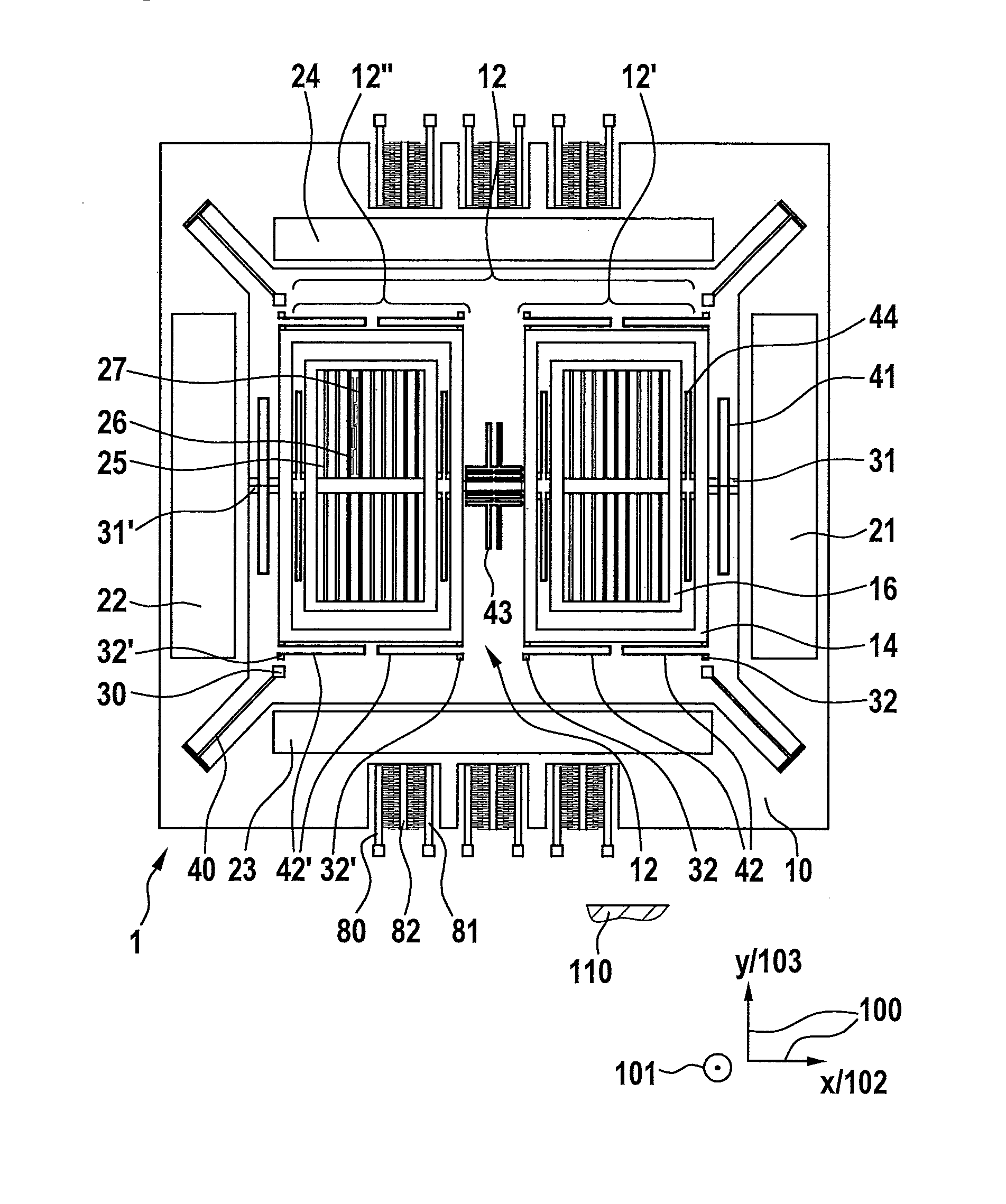
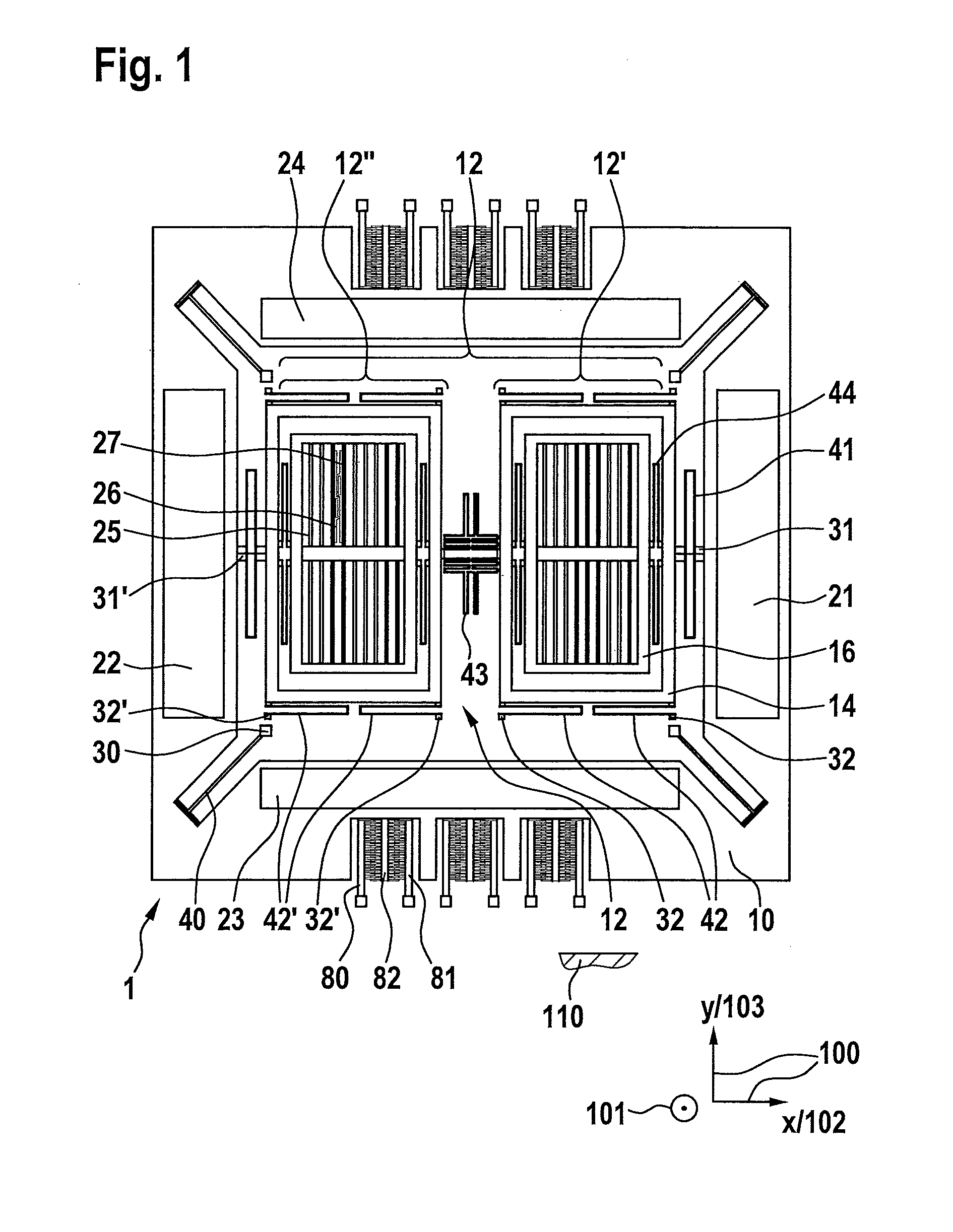
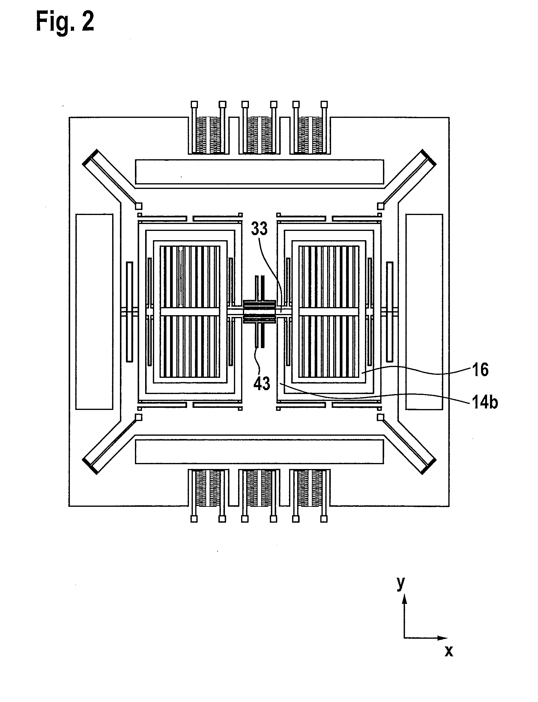
[0018]In the various figures, the same parts are always provided with the same reference numerals and therefore will generally be mentioned and explained only once each.

[0019]FIG. 1 shows a schematic diagram of a micromechanical structure according to the present invention, in particular a yaw rate sensor. The micromechanical structure is labeled with reference numeral 1 on the whole. Micromechanical structure 1 has a substrate, which is shown only schematically and is labeled with reference numeral 110. Substrate 110 has a main plane of extent 100, which is indicated schematically at the lower right of FIG. 1 with a second direction 102 and a third direction 103 as well as axial notation x for second direction 102 and y for third direction 103. A first direction 101 is to be imagined as perpendicular to main plane of extent 100 and is also provided with notation z. Micromechanical structure 1, which is designed in particular as a yaw rate sensor, in particular as a dual-channel or ...


PUM


Abstract

Micromechanical structure, in particular a yaw rate sensor having a substrate including a main plane of extent for detecting a first yaw rate about a first direction perpendicular to the main plane, a second yaw rate about a second direction parallel to the main plane, and a third yaw rate about a third direction parallel to the main plane and perpendicular to the second direction, includes a rotational oscillating element driven to rotational oscillation about a rotational axis parallel to the first direction. The micromechanical structure includes a yaw rate sensor configuration for detecting the first yaw rate that is completely surrounded by the rotational oscillating element in a plane parallel to the main plane. The micromechanical structure includes at least one first connection of the yaw rate sensor configuration on the rotational oscillating element, and at least one second connection of the yaw rate sensor configuration on the substrate.

Description

CROSS REFERENCE TO RELATED APPLICATION[0001]The present application claims priority to Application No. DE 10 2012 219 511.4, filed in the Federal Republic of Germany on Oct. 25, 2012, which is expressly incorporated herein in its entirety by reference thereto.FIELD OF INVENTION[0002]The present invention is directed to a micromechanical structure.BACKGROUND INFORMATION[0003]Micromechanical structures and yaw rate sensors are known from the related art. For several years, such configurations have been manufactured in mass production for numerous applications in the automotive field and the consumer electronics field, among other things. The number of units of multiaxial yaw rate sensors manufactured has recently increased significantly. In the consumer electronics field, this relates in particular to triple-axle or triple-channel yaw rate sensors and micromechanical structures. In addition to aspects with regard to accuracy and the performance of the micromechanical structures otherw...

Claims


Application Information

Patent Timeline
IPC IPC(8): G01C19/5712
CPCG01C19/5712
Inventor CLASSEN, JOHANNESSCHEBEN, ROLF
Owner ROBERT BOSCH GMBH
Why Eureka
Try Eureka