

Medical elongate member, method of manufacturing the same, and apparatus for manufacturing the same
a technology of elongate member and elongate body, which is applied in the direction of guide wires, applications, catheters, etc., can solve the problems of difficult operation (steering) of guide wires, weakened durability of guide wires, and uneven distribution of particulate materials on the surface of fluororesin coating layers, etc., to achieve low sliding resistance, low sliding resistance, and high strength
- Summary
- Abstract
- Description
- Claims
- Application Information
AI Technical Summary
Benefits of technology
Problems solved by technology
Method used
Image

Examples
first embodiment
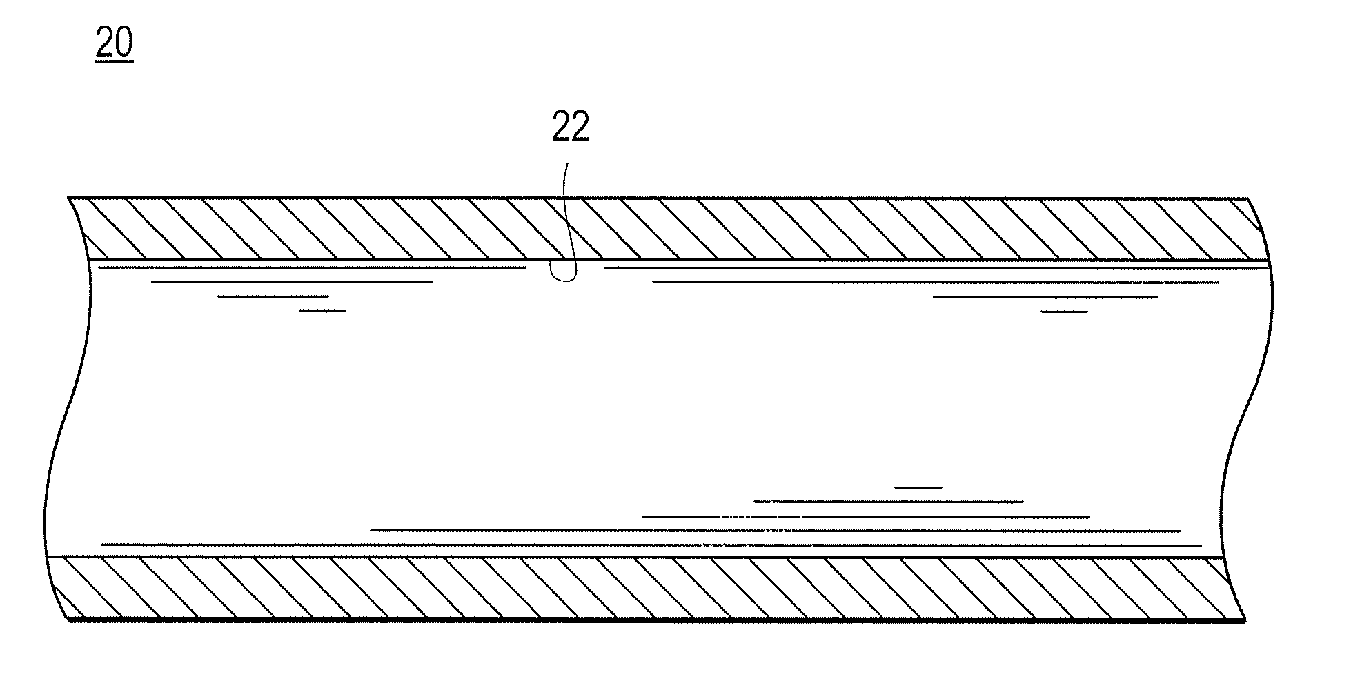
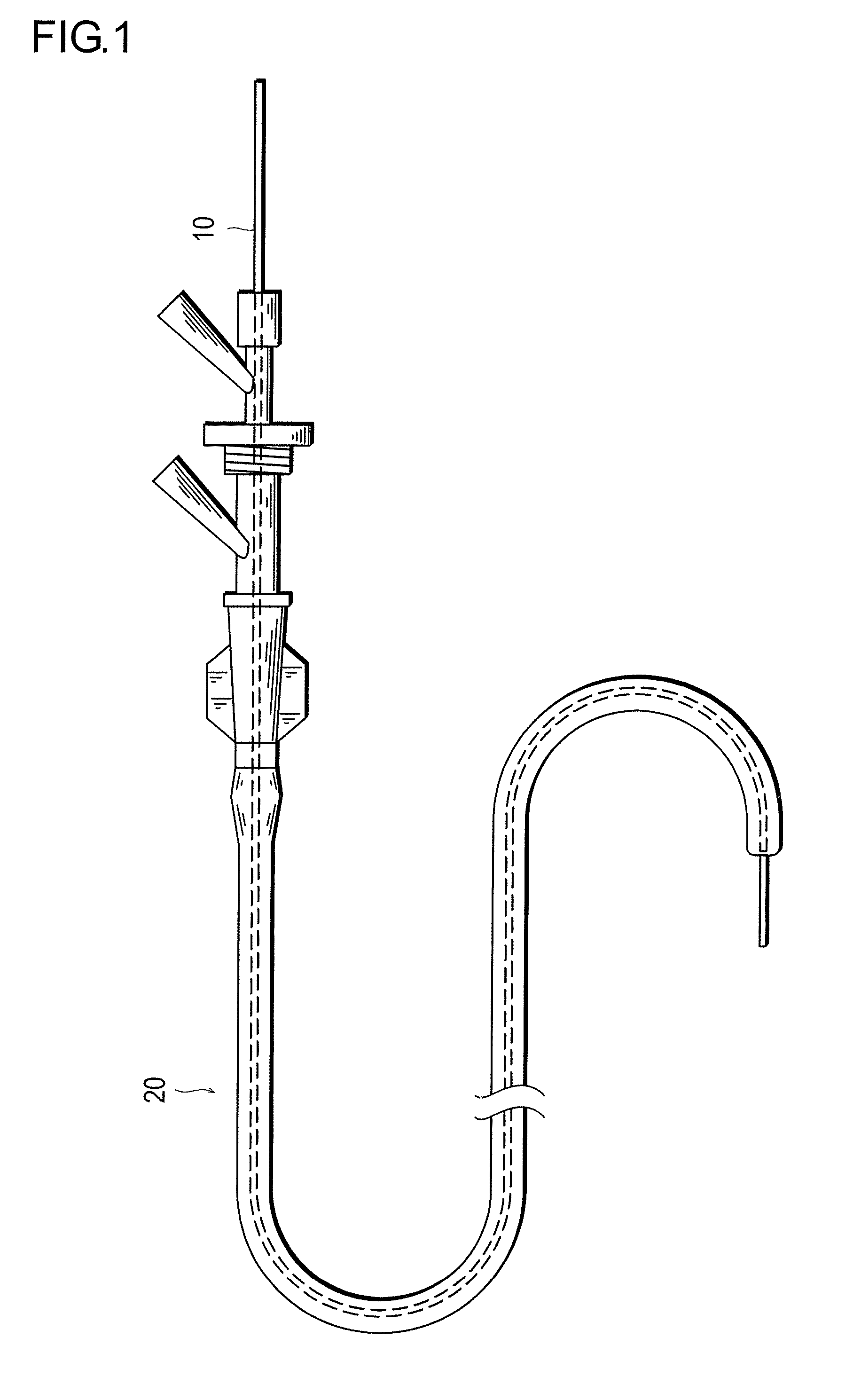
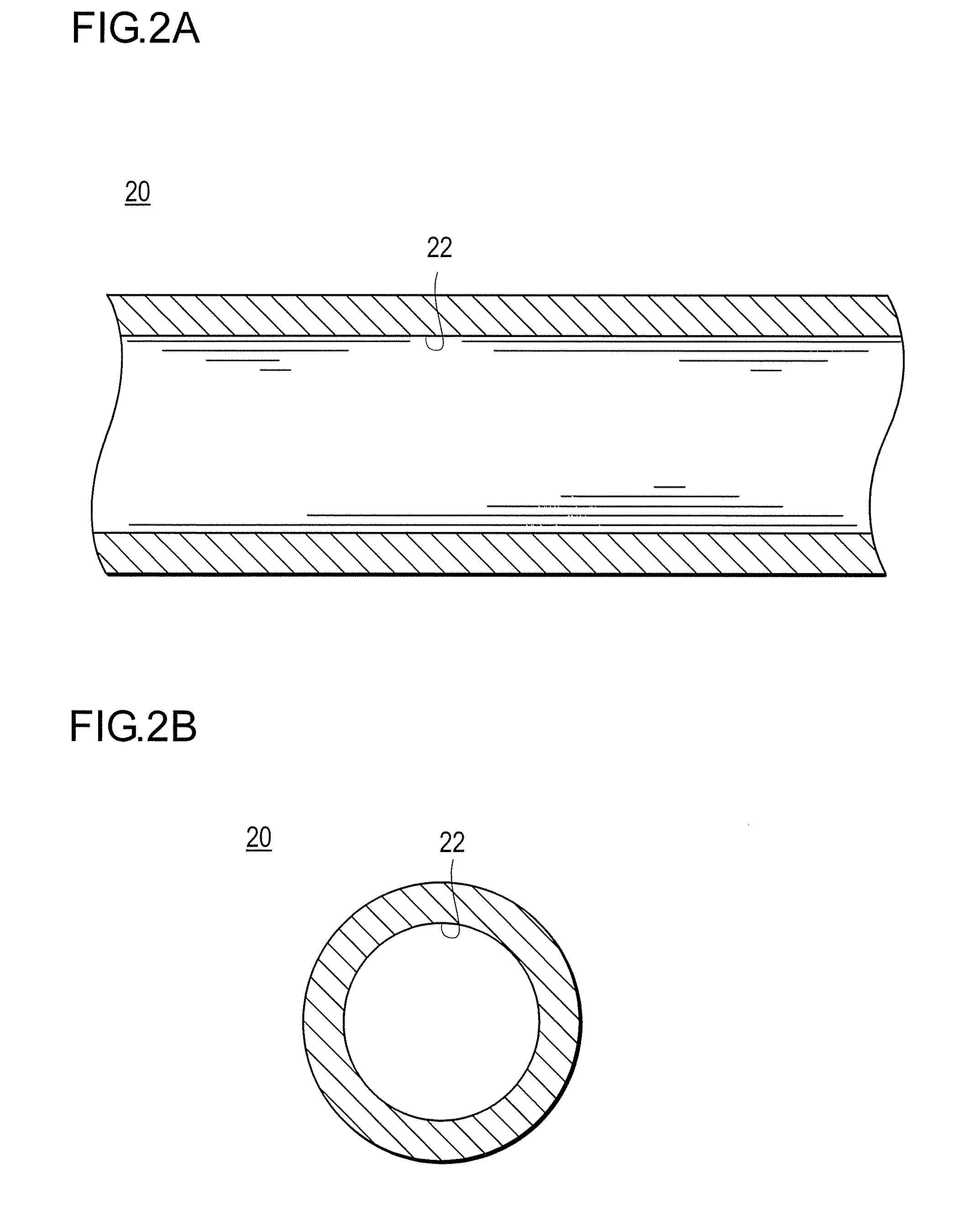
[0041]FIG. 1 is a schematic view showing a guide wire inserted in a catheter, FIGS. 2A and 2B show partial sectional views of the catheter. Incidentally, FIG. 2A is a sectional view taken in parallel to the axial direction of the catheter, and FIG. 2B is a sectional view taken perpendicularly to the axial direction of the catheter.
[0042]As shown in FIG. 1, the guide wire 10 is capable of passing through a lumen formed along the axial direction in the inside of the catheter 20. An operator can move the guide wire 10 distally and proximally (forwards and backwards) in the catheter 20 by holding the proximal end of the guide wire 10 and moving it distally and proximally.
[0043]The catheter 20 has a flexible tubular body, and, as shown in FIGS. 2A and 2B, is provided with a lumen 22 in its substantially central part and over the whole length of its body. The catheter 20 is inserted, for example, into a blood vessel in a living body and is guided to a diseased portion by the guide wire 10...
modification example 1
of Guide Wire
[0072]In the first embodiment above, as shown in FIG. 7, the projections 144 have been tetragonal as views sideways in relation to the projecting direction.
[0073]FIG. 8 illustrates hemispherical projections formed in the surface of a guide wire.
[0074]As shown in FIG. 8, the projections 144 may be formed in a hemispherical shape as viewed sideways in relation to the projecting direction. In this case, the recesses of the dies in the working apparatus are designed to be hemispherical in shape. Here, air vents are formed in the bottom parts of the recesses in the dies. Consequently, a shape of the projections 144 coinciding with the shape of the recesses in the dies can be obtained.
modification example 2
of Guide Wire
[0075]FIG. 9 illustrates another embodiment of the shape of the projections, FIG. 10 is a sectional view of a die in the working apparatus, and FIG. 11 illustrates the manner in which the projections make contact with the inner surface of a catheter.
[0076]In Modification Example 2, the projections 144 are provided with finer projections 148 in their surfaces. For forming the finer projections 148, as shown in FIG. 10, the recesses 32 in the dies 30 of the working apparatus are each formed in a shape with which the projection 144 and the finer projections 148 coincide. Here, for the formation of the finer projections 148, the resin of the guide wire 20 has to flow into finer recesses 322. For this purpose, air vents 34 are formed at the recesses 32, particularly at the finer recesses 322, of the dies 30. This ensures that when the dies 30 are pressed against the guide wire 20, the resin can flow also into the finer recesses 322, whereby a projection shape as shown in FIG...
PUM
| Property | Measurement | Unit |
|---|---|---|
| inclination angles | aaaaa | aaaaa |
| diameter | aaaaa | aaaaa |
| melting point | aaaaa | aaaaa |
Abstract
Description
Claims
Application Information