
Lubricant management system

Active Publication Date: 2014-05-01
DANA AUTOMOTIVE SYST GRP LLC
View PDF15 Cites 6 Cited by
  • Summary
  • Abstract
  • Description
  • Claims
  • Application Information

AI Technical Summary

Benefits of technology

The present invention is a lubricant management system for an axle housing that can vary the amount of lubricant used. The system includes a housing and a valve, which can be adjusted to control the flow of lubricant. This allows for better management of lubricant usage, reducing the amount of lubricant wasted and ensuring optimal performance of the vehicle's axle.

Problems solved by technology

For example, the volume of lubricant disposed in the sump may be too large in many instances.
During ordinary operation of a vehicle including the drive axle, when torque loads are well below a maximum amount, the volume of lubricant may result in excess windage of the drive pinion, the differential assembly, and the pair of axles.
Additionally, during operation in cold weather, the volume of lubricant may disperse heat generated between the moving parts at a rate which prevents a viscosity of the volume of lubricant from decreasing, resulting in excess windage.
Simply reducing the volume of lubricant disposed in the sump to reduce windage results in many unintended consequences.
During a torque intensive operation of a vehicle including the drive axle, when torque loads are at or near a maximum amount, a reduced volume of lubricant may not adequately reduce the friction generated by the drive pinion, the differential assembly, and the pair of axles.
As a result, the components may wear excessively and operate in a noisy or harsh manner.
Additionally, during operation of the axle housing using the reduced volume of lubricant, the lubricant may be unable to disperse heat generated between the moving parts at a rate which prevents premature degradation of the lubricant or damage to seals used in the axle housing.

Method used


Image

  • Lubricant management system
  • Lubricant management system
  • Lubricant management system

Examples


Embodiment Construction

[0025]It is to be understood that the invention may assume various alternative orientations and step sequences, except where expressly specified to the contrary. It is also to be understood that the specific devices and processes illustrated in the attached drawings, and described in the following specification are simply exemplary embodiments of the inventive concepts defined herein. Hence, specific dimensions, directions or other physical characteristics relating to the embodiments disclosed are not to be considered as limiting, unless expressly stated otherwise.

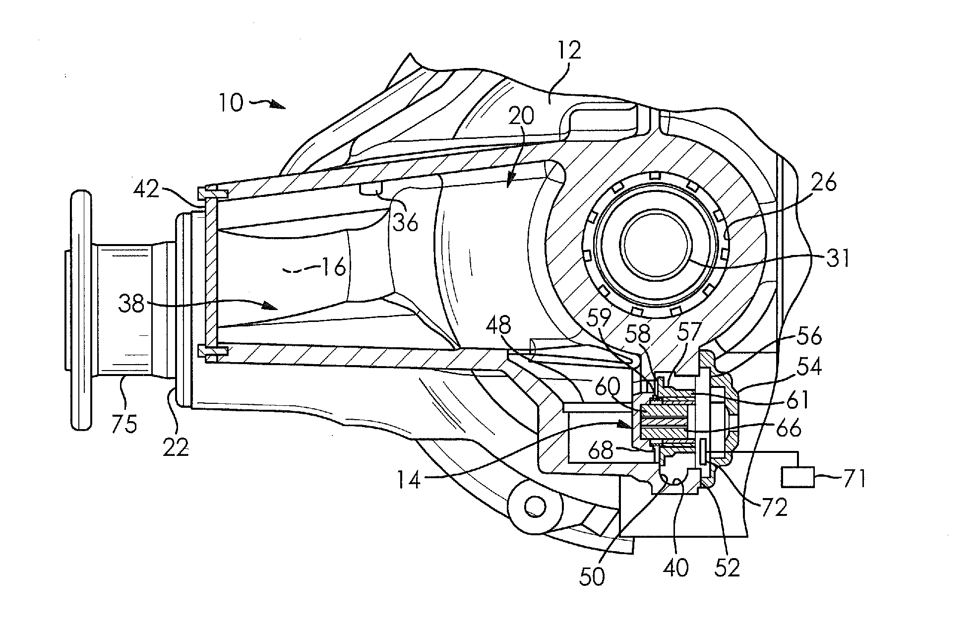
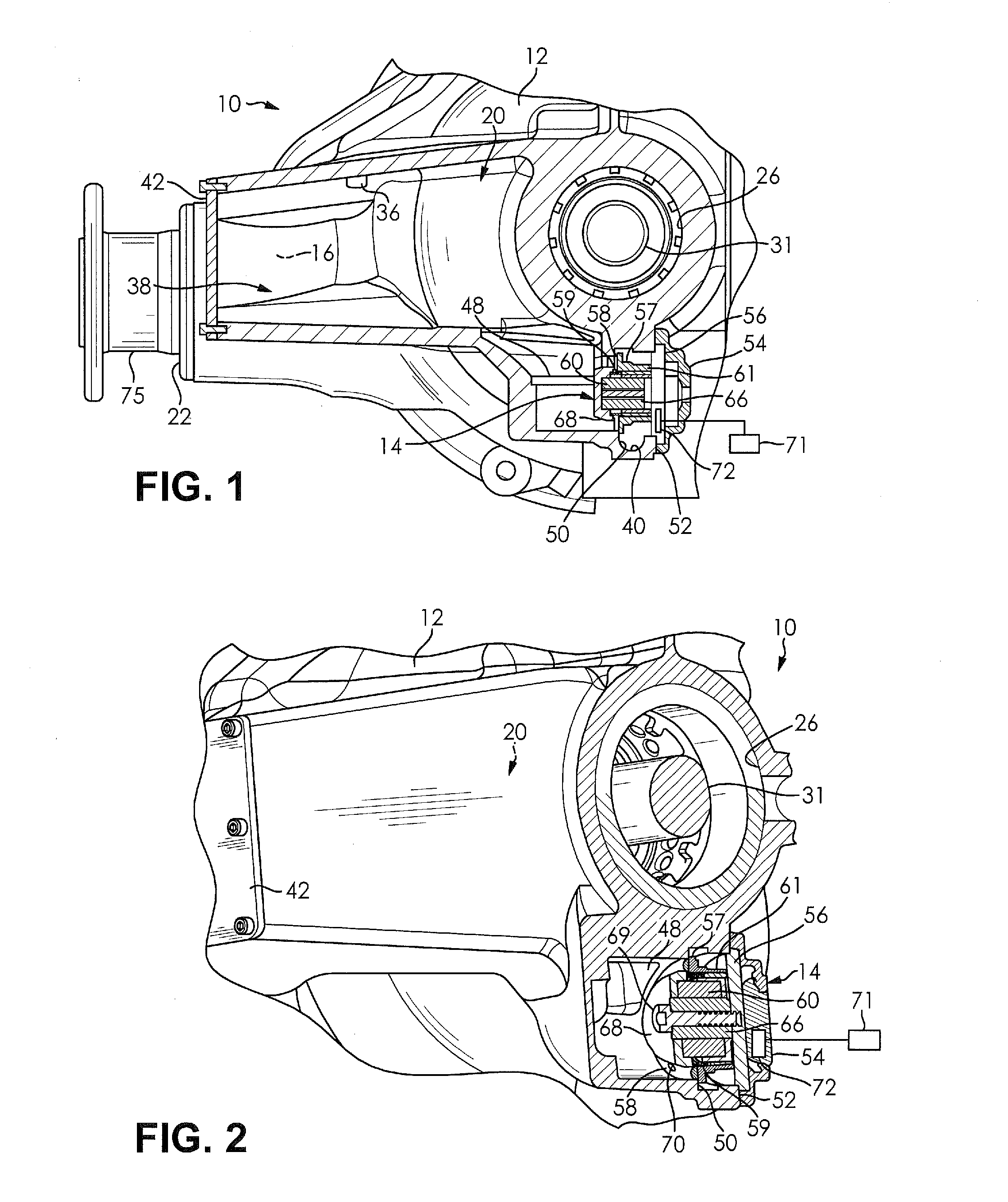
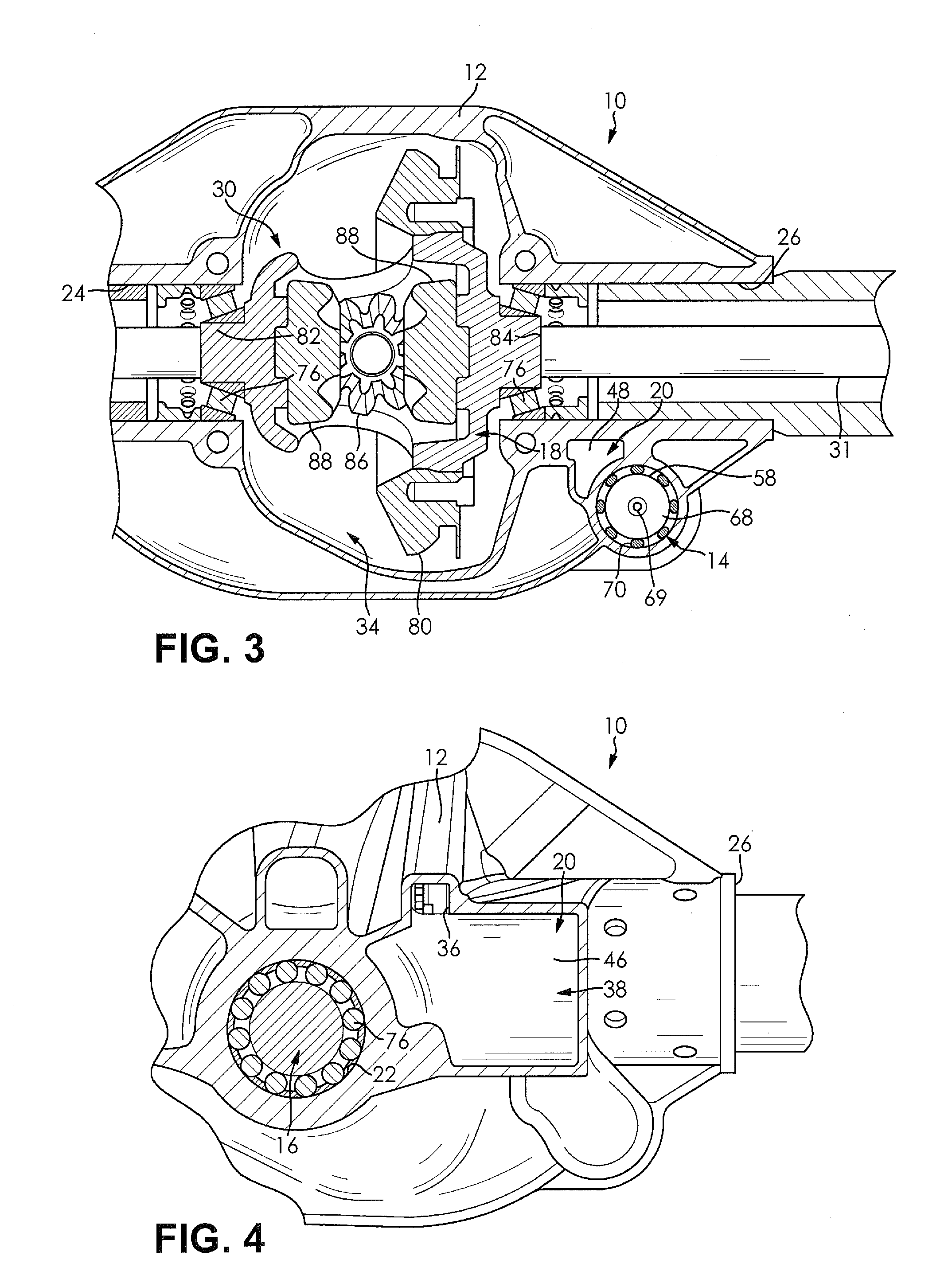
[0026]FIGS. 1-6 illustrate a lubricant management system 10 for a vehicle according to an embodiment of the present invention. The lubricant management system includes a housing 12, a valve 14, a first power transmitting component 16, and a second power transmitting component 18. The lubricant management system 10 forms a portion of a vehicle drivetrain; however, the lubricant management system 10 may be used in other appl...


PUM


Abstract

A lubricant management system for a vehicle is provided. The lubricant management system includes a housing, a power transmitting component, and a valve. The housing defines a lubricant passage therethrough. The power transmitting component is rotatingly disposed in the housing. The valve is at least partially disposed in the lubricant passage and has a first position and a second position. The valve in the first position militates against a flow of lubricant from a first portion of the housing to a second portion of the housing and the valve in the second position facilitates the flow of lubricant from the first portion of the housing to the second portion of the housing. The lubricant management system varies an amount of lubricant used in a sump of the housing in a simple and cost effective manner.

Description

CLAIM OF PRIORITY[0001]The present application claims the benefit of priority to U.S. Provisional Application No. 61 / 718,742 filed on Oct. 26, 2012, which is incorporated herein in its entirety by reference.FIELD OF THE INVENTION[0002]The present invention relates to power transmission components and more specifically to gear lubrication systems.BACKGROUND OF THE INVENTION[0003]Conventionally, axle housings for a drive pinion, a differential assembly, and a pair of axles define a sump into which a volume of lubricant is disposed. The volume of lubricant reduces friction between the drive pinion and a ring gear of the differential assembly, between a pair of side gears and at least a pair of pinion carrier gears, and between components of a plurality of bearings disposed in the axle housing. In addition to reducing friction, the volume of lubricant also disperses heat generated between the moving parts. Depending on a temperature of the axle housing (which may be influenced by an amb...

Claims


Application Information

Patent Timeline
IPC IPC(8): F16H57/04
CPCF16H57/045F16H57/0447F16H57/0483F16H57/0409F16K31/0606F16K31/0651
Inventor PAIELLI, PERRY M.CREECH, MIKE Z.
Owner DANA AUTOMOTIVE SYST GRP LLC
Learn More