Current control circuit and method thereof for a power converter

a power converter and control circuit technology, applied in the direction of power conversion systems, dc-dc conversion, instruments, etc., can solve the problems of circuit failure, circuit instability, circuit efficiency reduction, etc., and achieve the effect of better system stability and response speed

Inactive Publication Date: 2014-05-01
LUXMILL ELECTRONICS
View PDF3 Cites 77 Cited by
  • Summary
  • Abstract
  • Description
  • Claims
  • Application Information

AI Technical Summary

Benefits of technology

[0009]In order to solve the problem aforementioned, the main objective of the present invention is to provide a current control circuit for a power converter. The circuit samples an inductor current passing the inductor in a current sampling circuit. The magnitude of the inductor current that is sampled is then modified by a gain factor and input to a modu

Problems solved by technology

However, it is easy to cause circuit unstable because of the effect of the loading variation.
However, the conventional power c

Method used


Image

  • Current control circuit and method thereof for a power converter
  • Current control circuit and method thereof for a power converter
  • Current control circuit and method thereof for a power converter

Examples


first embodiment

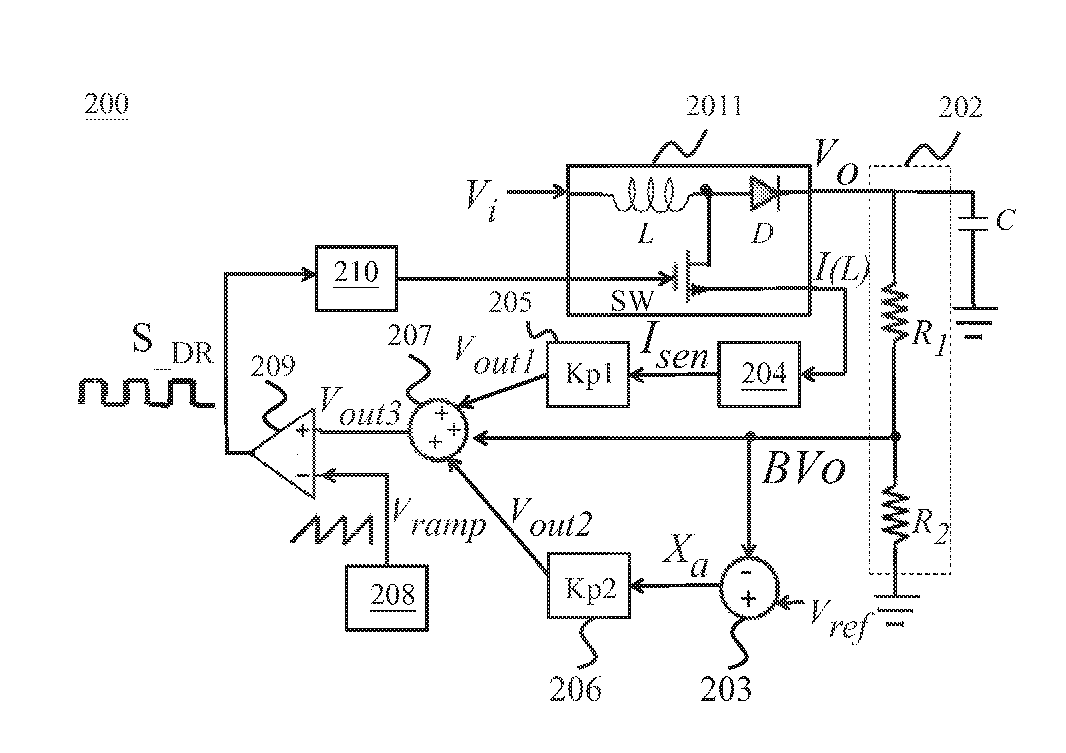
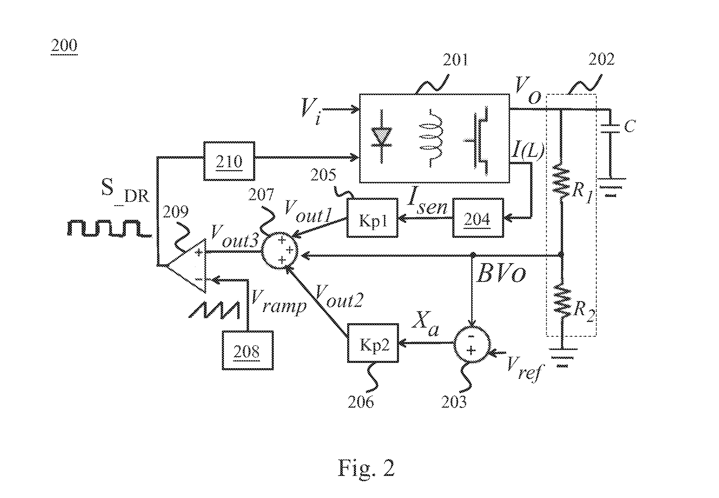
[0029]Now, please refer to FIG. 4, which is a structural view illustrating the current control circuit in the present invention. As shown in FIG. 4, the current control circuit 200 includes a Boost converter 2011, a voltage divider circuit 202, a differential amplifier 203, a current sampling circuit 204, a first gain circuit 205, a second gain circuit 206, an adder 207, a saw tooth generator 208, a modulation comparator 209 and a driver 210. The Boost converter 2011 consists of an inductor L, a diode D, and a switch and configure to receive and convert an input voltage Vi to generate an output voltage V0 to a capacitance C. A voltage divider circuit 202 is electrically connected to the capacitance C and generates a feedback voltage BV0 (where B=R2 / (R1+R2)) in accordance with the output voltage of the converter. The voltage divider circuit 202 includes a first resistor R1 electrically connected to the output voltage V0 and a second resistor R2 electrically connected between the firs...

second embodiment

[0031]Now, please refer to FIG. 5, which is a structural view illustrating the current control circuit in the present invention. As shown in FIG. 5, the current control circuit 200 includes a Buck converter 2012, a voltage divider circuit 202, a differential amplifier 203, a current sampling circuit 204, a first gain circuit 205, a second gain circuit 206, an adder 207, a saw tooth generator 208, a modulation comparator 209 and a driver 210. The Buck converter consists of an inductor L, a first switch SW1 and a second switch SW2 and configured to receive and convert an input voltage Vi to generate an output voltage Vo to a capacitance C. A voltage divider circuit 202 is electrically connected to the capacitance C and generates a feedback voltage BV0 (where B=R2 / (R1+R2)) in accordance with the output voltage of the converter. The voltage divider circuit 202 includes a first resistor R1 electrically connected to the output voltage V0 and a second resistor R2 electrically connected bet...


PUM


Abstract

A power converter used in the current control circuit and control method, consisting of a converter, a voltage divider circuit, a current sampling circuit, a first gain circuit, a differential amplifier, a second gain circuit, a multiplier, a saw tooth wave generator, a modulation comparator, and a driver. The invention samples inductor current through the current sampling circuit and generates the current sense signal, then processes again. With the differential amplifier, it compares the feedback voltage from the voltage divider circuit with the reference voltage, and the results along a modulation comparator output a drive signal to control the duty cycle in order to avoid the generation of inrush current. The present invention avoids inrush current caused by the large drive signal and achieves a good response rate and better system stability.

Description

BACKGROUND OF THE INVENTION[0001]1. Field of the Invention[0002]The present invention is related to a current circuit and method thereof and more particularly related to a current control circuit and method thereof for a power converter, which implements a current sampling circuit to sample an inductor current passing through the current control circuit of the power converter so as to be able to control the output duty cycle ratio. As a result, the occurrence of inrush current is restrained. The present invention provides a better response speed and better system stability.[0003]2. Description of the Prior Art[0004]Because of continuing development of the modern technology and the popularity of the electronic devices, power converters play an important role to the electronic devices. A power converter is to convert power to suitable voltage as needed by the electronic devices, such as computers, display monitors, DVD players, and so on.[0005]FIG. 1 is a view illustrating a conventio...

Claims


Application Information

Patent Timeline
IPC IPC(8): H02M7/217
CPCH02M7/217H02M1/36H02M3/158H02M1/0009H02M1/009
Inventor CHANG, YU-CHENGLAN, MAO-FENGLIN, CHUNG-HUNG
Owner LUXMILL ELECTRONICS
Why Eureka
Try Eureka