Exposing Fibers in Composite Laminates

a technology of fiber reinforced resin and composite laminates, which is applied in the direction of synthetic resin layered products, packaging, fastening means, etc., can solve the problems of insufficient preparation of surface preparation of bonding parts, small margin of error when bonding parts, and crack propagation along bonding lines. , to achieve the effect of reducing or completely eliminating the need for mechanical fasteners, sufficient robustness and reliabl

Active Publication Date: 2014-05-01
THE BOEING CO
View PDF3 Cites 25 Cited by
  • Summary
  • Abstract
  • Description
  • Claims
  • Application Information

AI Technical Summary

Benefits of technology

[0007]The disclosed embodiments provide a method of exposing reinforcing fibers of fiber reinforced laminates. The reinforcing fibers may be exposed only along surfaces of the laminate, or throughout the entire thickness of the laminate. In one embodiment, exposing the reinforcing fibers along a surface of laminates allows faying surfaces of two laminate parts to be bonded together such that the exposed fibers of the two parts interpenetrate and allow the formation of a bonded lap joint suitable for high-performance applications. In another embodiment, exposing the reinforcing fibers throughout the entire thicknesses of two laminate parts allows the parts to be joined together by a bonded butt joint. The bonded joint is sufficiently robust and reliable such the need for mechanical fasteners may be reduced or completely eliminated for some applications. Bonded joints are achieved having improved strength and crack resistance due to the fact that the joints are formed by a volume of cured adhesive that envelops reinforcing fibers of both laminate parts through a substantial thickness. In contrast, traditional bonded joints rely on only a relatively thin layer of bonding adhesive that does not envelop the reinforcing fibers. A displacement gel used to expose the reinforcing fibers may also be employed to expose portions of a fiber preform reinforcement used in resin infusion processes. The disclosed method of exposing the reinforcing fibers may be easily carried out and integrated into conventional processes for laying up and curing laminate parts.

Problems solved by technology

However, surface preparation must be near perfect and the margin for error when bonding the parts is quite small because the bonded area, commonly referred to as a bondline, is relatively thin and does not substantially encompass the reinforcing fibers of the laminate parts.
Cracks may propagate along surfaces of bondlines that are not adequately prepared before bonding.
The use of mechanical fasteners is undesirable, however, because they add weight to the structure, require additional material and labor, and may necessitate the use of higher volumes of reinforcing fibers in order to compensate for possible weakening of the structure due to the presence of fastener holes.

Method used


Image

  • Exposing Fibers in Composite Laminates
  • Exposing Fibers in Composite Laminates
  • Exposing Fibers in Composite Laminates

Examples


Embodiment Construction

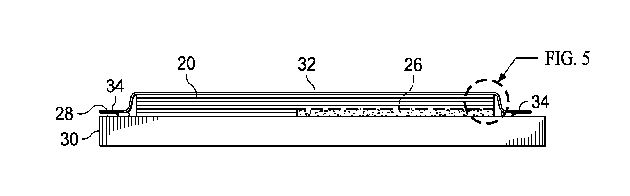
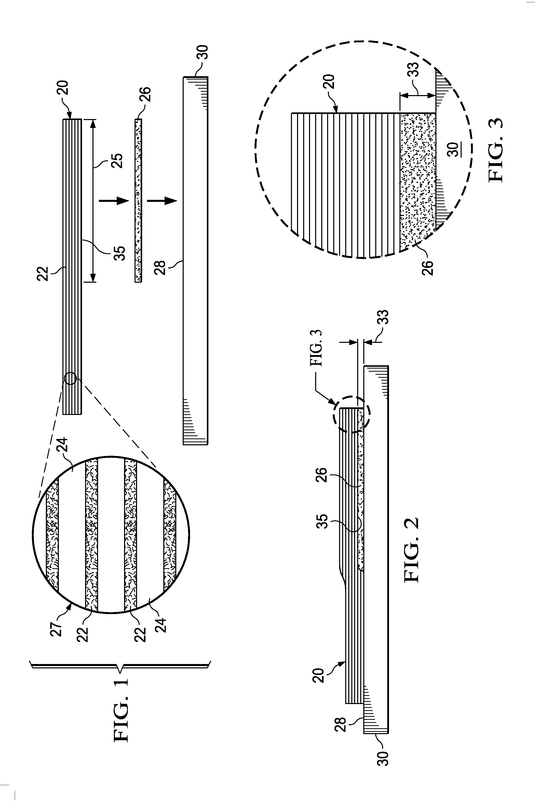
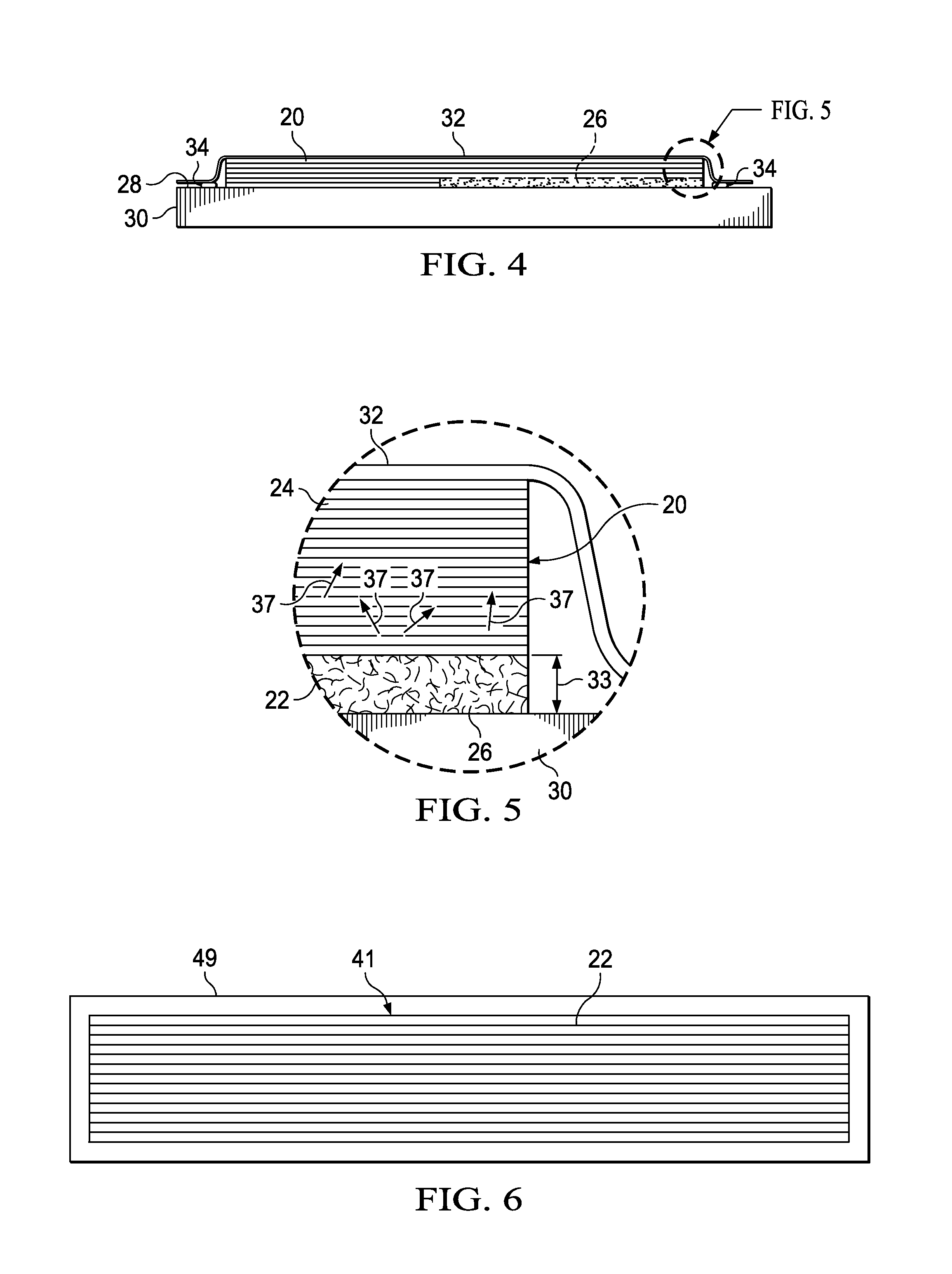
[0042]Referring first to FIG. 1, in one aspect, the disclosed embodiments relate to a method of exposing fibers 22 in a section 25 of a fiber reinforced resin laminate 20, which may be, for example, a pre-preg. As shown in the enlargement 27, an uncured laminate 20 may comprise a layup of pre-preg plies of a suitable resin matrix 24 reinforced with unidirectional or bidirectional reinforcing fibers 22. The fibers 22 may comprise any material suitable for the application, such as, without limitation, carbon, and the resin 24 may comprise a compatible polymer, such as, without limitation epoxy. Other fibers22 and resins 24 are possible, including fiber reinforced thermoplastic resins. As will be discussed below in more detail, the section 25 of the laminate 20 where the fibers 22 are to be exposed may be a faying surface 35 that is intended to be joined to the faying surface 35 of another laminate in a secondary bonding operation.

[0043]In order to expose the reinforcing fibers 22 in a...


PUM

PropertyMeasurementUnit
viscosityaaaaaaaaaa
temperatureaaaaaaaaaa
solventaaaaaaaaaa

Abstract

Fibers in a fiber reinforced resin laminate are exposed by placing a gel in contact with the resin laminate, forcing the fibers of the resin laminate into the gel, and using the gel to displace the resin surrounding the fibers being forced into the gel. The gel is removed to expose the fibers.

Description

BACKGROUND INFORMATION[0001]1. Field[0002]This disclosure generally relates to the fabrication of fiber reinforced resin laminates, and deals more particularly with a method of exposing the reinforcing fibers in a laminate. The disclosure also relates to a method of bonding fiber reinforced resin laminates.[0003]2. Background[0004]Several techniques are commonly used to join the faying surfaces of composite parts, such as fiber reinforced resin laminates. For example, faying surfaces of laminate parts may be joined together by compressing and co-curing them together. A relatively strong joint may be achieved by co-curing the laminates because the resin matrix along the faying surfaces of the parts flow together, consolidate and may cross-link during the curing process. Alternatively, faying surfaces of two pre-cured laminate parts may be joined together with a bonded joint using a bonding adhesive that is cured while the parts are compressed together, otherwise known as co-bonding a...

Claims


Application Information

Patent Timeline
Patent Type & Authority Applications(United States)
IPC IPC(8): B32B38/10B32B37/12B32B27/04
CPCB29C66/721B29C65/4835B29C66/02B29C66/112B29C66/1122B29C66/114B29C66/1142B29C66/43B29C66/73941B29C66/72141B29C66/73756B29C66/7212B29C66/72143B29C66/7392B29C66/7394B29C66/71Y10T403/477Y10T156/10Y10T428/24994B29C70/54B29K2307/04B29K2063/00
Inventor MOSELAGE, III, JOHN HENRY
Owner THE BOEING CO
Why Eureka
Try Eureka