
Magnitude and phase response calibration of receivers

a receiver and magnitude technology, applied in the field of wideband radio frequency receivers, can solve the problems of amplitude and phase response, and affect the calibration process

Inactive Publication Date: 2014-05-01
TEKTRONIX INC
View PDF0 Cites 4 Cited by
  • Summary
  • Abstract
  • Description
  • Claims
  • Application Information

AI Technical Summary

Benefits of technology

The present invention has advantages and innovative features that are described in detail in the description, accompanying claims, and drawings.

Problems solved by technology

Further, as components age the amplitude and phase response also may be affected.

Method used


Image

  • Magnitude and phase response calibration of receivers
  • Magnitude and phase response calibration of receivers
  • Magnitude and phase response calibration of receivers

Examples


Embodiment Construction

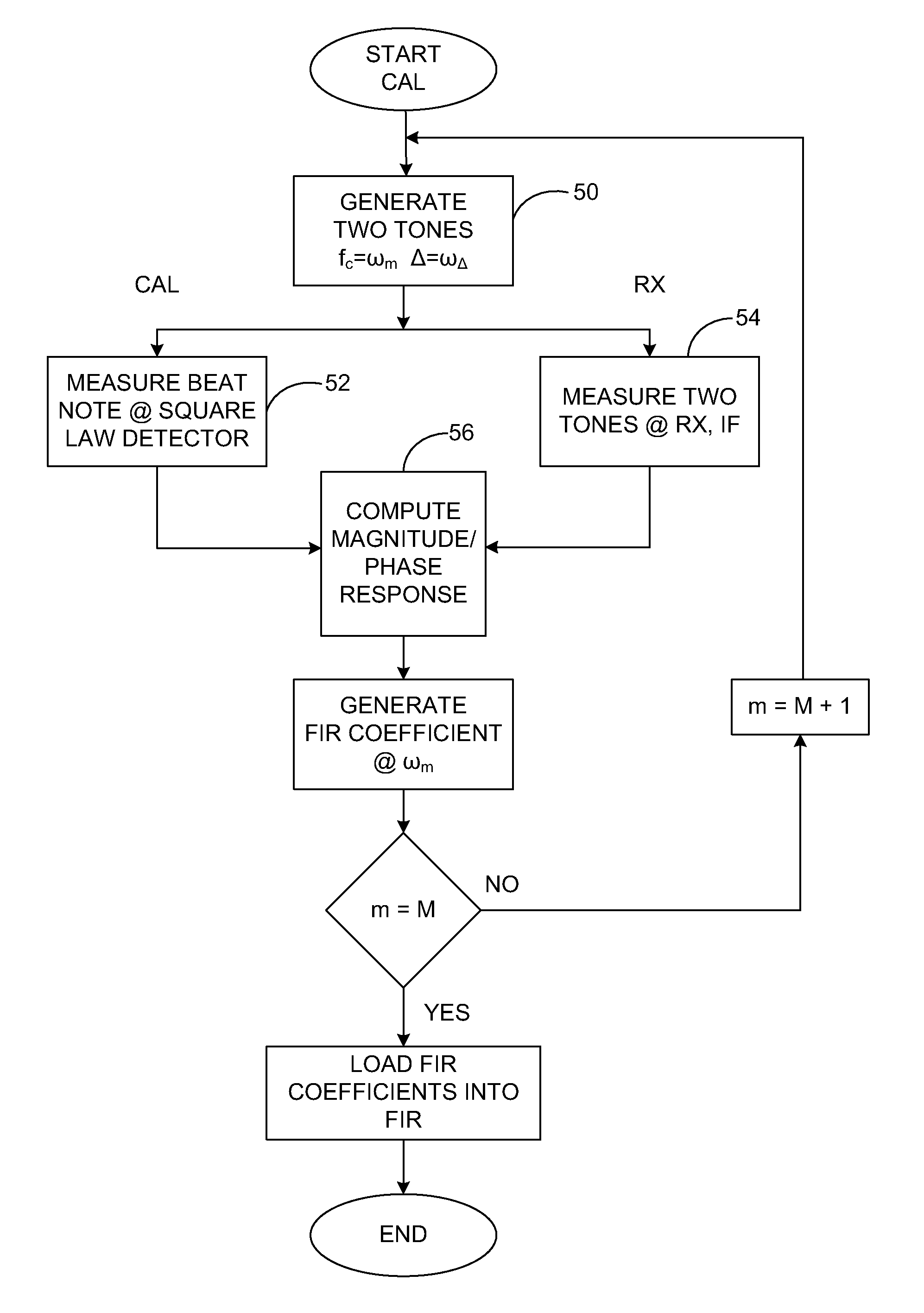
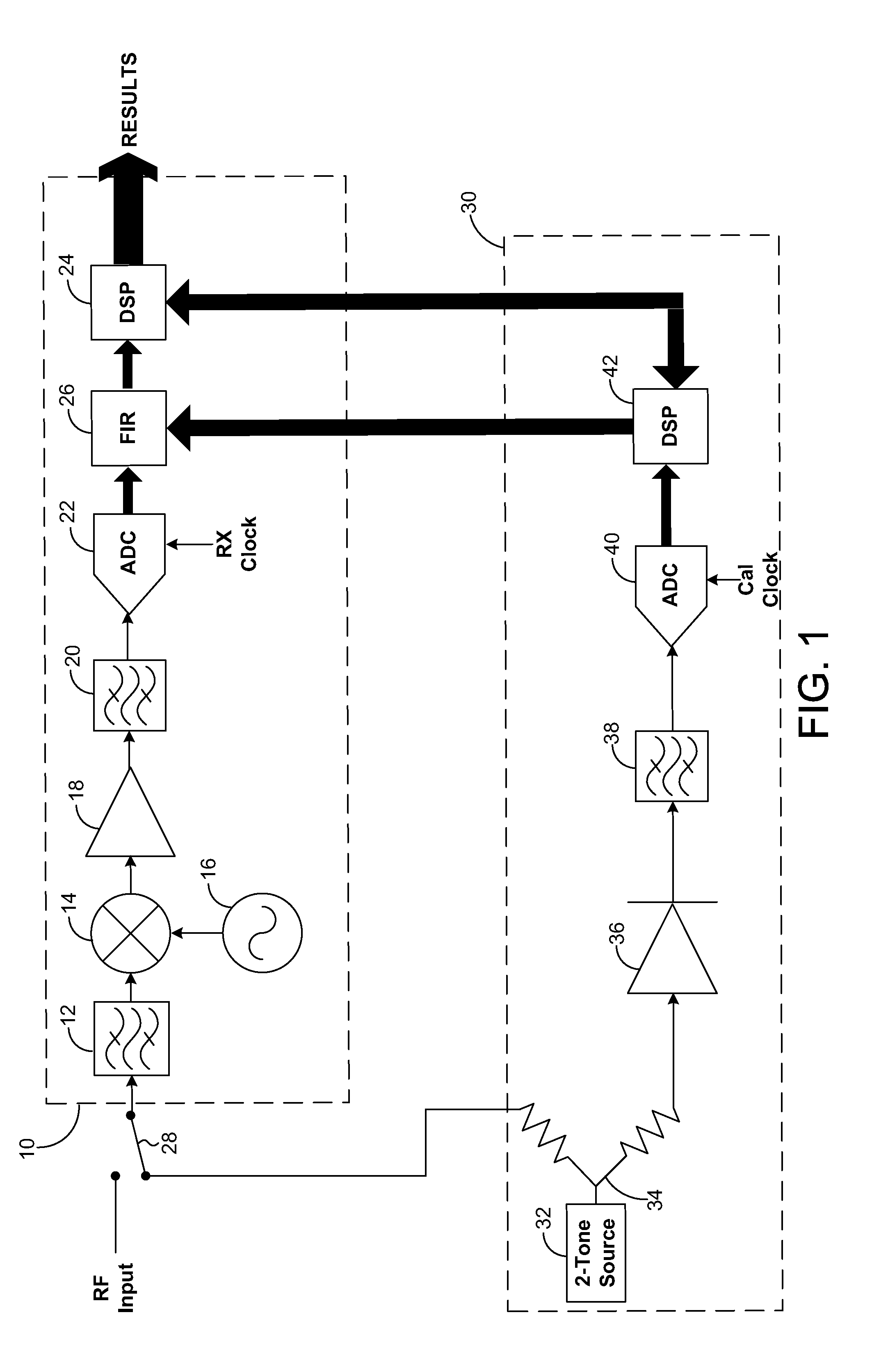
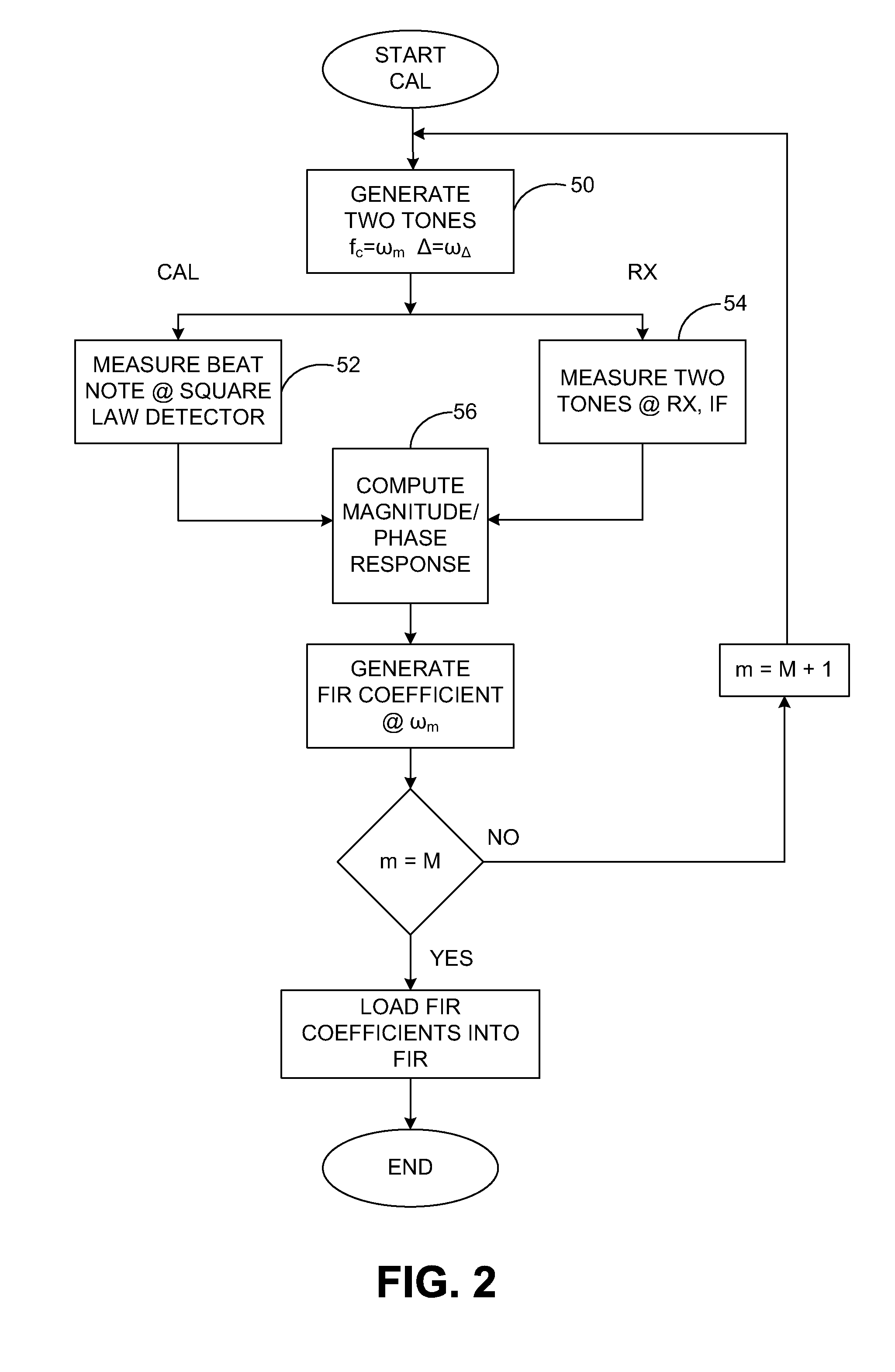
[0009]Referring again to FIG. 1, an integrated calibrator 30 is shown in conjunction with the RF receiver 10. A two-tone source 32 produces two frequencies, or tones, separated by a fixed frequency. The two tones are stepped together across a wideband frequency range for the RF receiver 10. A symmetric broadband power divider 34 splits the two-tone signal from the two-tone source 32 to provide two identical signals, one of which is fed to the RF receiver input via a switch 28 and the other of which is fed to a calibrated diode 36 operating as a square law detector. Along with the usual amplitude information obtainable from the diode 36, a beat note at a frequency equal to the difference of the frequencies of the two tones is generated by the diode. The beat note contains both phase and magnitude phase information about the signals. The phase information is used in an algorithm to measure the phase response of the receiver signal path, as described below. A practical implementation o...


PUM


Abstract

An integrated calibrator provides for magnitude and phase response calibration of RF receivers to produce amplitude flatness and phase linearity across the frequency range of the RF receiver by using a simple square law diode detector and a frequency-stepped two-tone source. A two-tone source generator provides two sinusoidal signals separated by a specified frequency delta about a center frequency. The center frequency is stepped across the bandwidth of the RF receiver. At each center frequency the two sinusoidal signals are input to the RF receiver and to the diode detector. The two sinusoidal signals are processed by both the receiver path and the calibrator path, and the results are used by the calibrator to generate coefficients for a correction filter in the receiver path at each of the stepped center frequencies.

Description

BACKGROUND OF THE INVENTION[0001]The present invention relates to wide-band radio frequency (RF) receivers, and more particularly to a system for calibrating wide-band RF receivers for amplitude flatness and phase linearity.[0002]Increased data bandwidth requirements have driven a need for RF receivers that not only receive signals with very wide-band modulation, but also that maintain a flat amplitude and linear phase response over a wide bandwidth. As shown in FIG. 1, a wide-band digital RF receiver 10 has an input for receiving multiple RF signals from an antenna or other source. An image reject filter 12 band-limits the signal prior to a mixer 14. The mixer 14 down-converts the band-limited signal, using a local oscillator 16, to an intermediate frequency (IF). The IF signal from the mixer 14 is input to an amplifier 18 and filter 20, and then digitized in response to a receiver clock by an analog-to-digital converter (ADC) 22 to produce a stream of digitized samples. The sample...

Claims


Application Information

Patent Timeline
Patent Type & Authority Applications(United States)
IPC IPC(8): H04B1/10
CPCH04B1/10H04B17/20H04B17/21H04B17/29
Inventor DA SILVA, MARCUS K.OLSEN, GORDON A.CROUCH, RICHARD A.BORDEN, FRANKLIN M.
Owner TEKTRONIX INC
Learn More