Three-dimensional-structure former

a three-dimensional structure and former technology, applied in the field of printed manufacturing, can solve the problems of difficult printing systems of many high-quality printing systems to print on thick stiff corrugated substrates, difficult to control the thickness of schemes, and high cost of corrugation forms, so as to achieve control of tensile strength and bending moment, the effect of less expensiv

Active Publication Date: 2014-05-01
EASTMAN KODAK CO
View PDF32 Cites 2 Cited by
  • Summary
  • Abstract
  • Description
  • Claims
  • Application Information

AI Technical Summary

Benefits of technology

[0040]Toner can be readily positioned precisely (e.g., within 1/600″) to form desired patterns, unlike glue or (especially) epoxy. Toner can also be substantially less expensive than epoxy.
[0041]In various aspects, multiple toner regions are used to control tensile strength and bending moment independently. Unlike glue, the size (thickness), contents (additives), and position of toner patterns can be readily controlled. Moreover, stiffness varies as the square of the second moment of inertia, or as thickness4. The direction of stiffness can be controlled by selecting an appropriate toner pattern. Unlike prior schemes using toner as an adhesive between surfaces substantially in contact with each other, various aspects desc...

Problems solved by technology

This form of corrugation is more expensive than conventional corrugation because of the increased use of polymeric materials and further suffers from weaknesses at the joints in that the joints are typically thin polymeric supports which are subject to lateral collapse when subjected to shear forces.
However, it is difficult for many high quality printing systems to print on thick stiff corrugated substrates, particularly using high volume presses that are intended for use with thinner more flexible roll fed web media.
However, these schemes are very limited in the thickness, and therefore in the mechanical strength, they can provide.
However, those properties cannot readily be adjusted depending on the type of product to be packaged.
This restricts the box designer's freedom to adjust the mechanical characteristics of the box based on its intended use.
This relative strength configuration cannot be provided by conventional corrugated materials.
Extra space in each box is filled with packing materials that add additional weight and cost.
In addition, maintaining an inventory of the packaging materials and boxes cost money and takes up space.
This requires that any desired product ...

Method used


Image

  • Three-dimensional-structure former
  • Three-dimensional-structure former
  • Three-dimensional-structure former

Examples


Embodiment Construction

[0061]As used herein, the terms “receiver,”“receivers,”“medium,”“media,”“recording medium,” and “recording media” are used interchangeably. “Receivers” (or any equivalent term) include objects extending (or that can be arranged to extend) significantly farther in two directions than in a third direction of three mutually-orthogonal directions. Most receivers have significant length and width, e.g., 8″×11″, but very little thickness, e.g., 4 mil (˜40.1 mm). “Sheet” and “web” receivers are used interchangeably except when discussing aspects that are particularly adapted to use one of those styles of receiver. “Adhere” is used herein both intransitively (toner adheres to paper) and transitively (toner adheres two sheets to each other, i.e., the adhesive forces between a toner mass and each of two sheets holds those two sheets together).

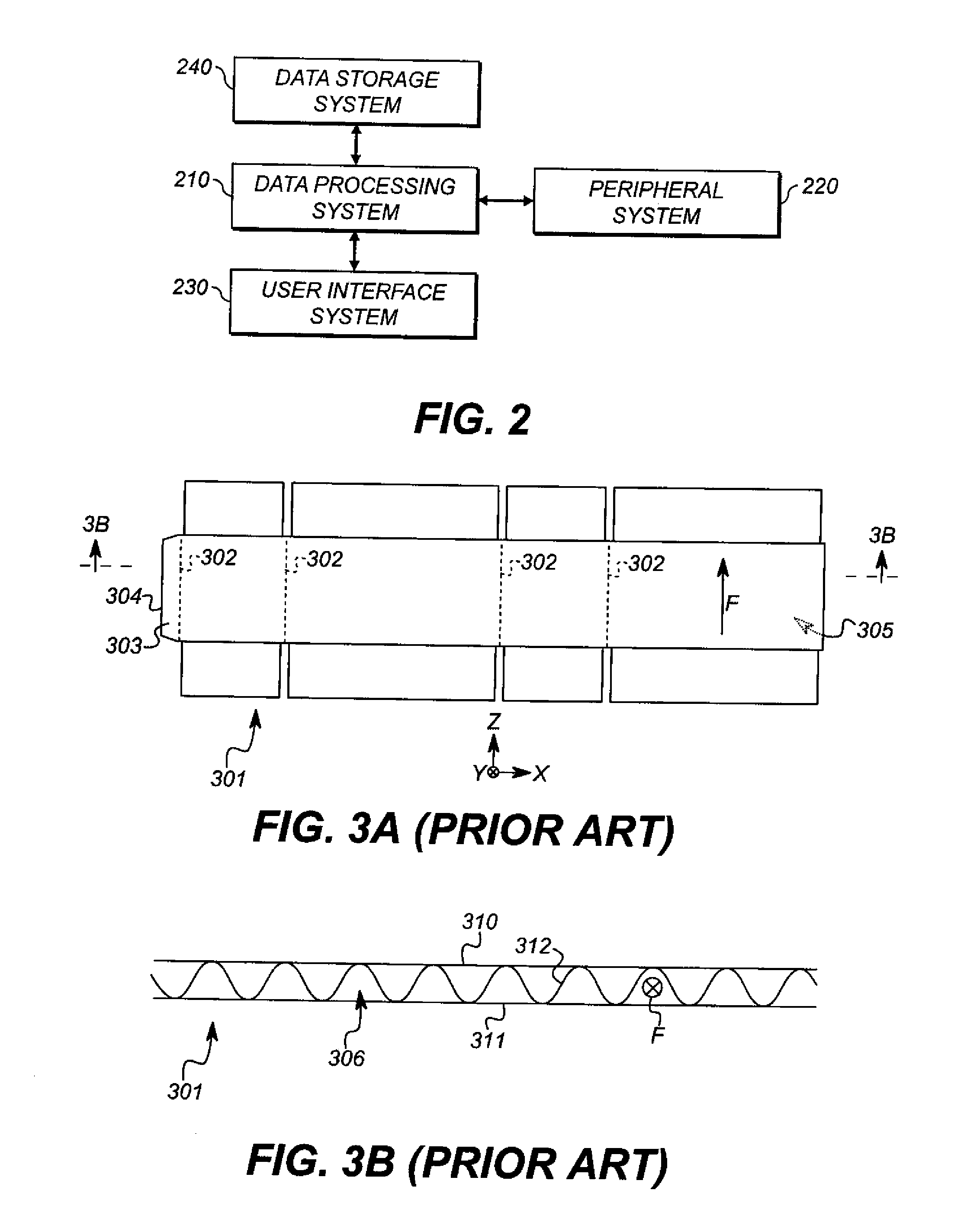
[0062]Referring back to FIG. 3B, the direction of extension F of flutes 306 is the direction in which a ray extended in direction F will not cross flute...


PUM


Abstract

A device for producing a three-dimensional structure from a receiver includes a deposition unit that deposits toner on the receiver. That unit is controlled by a controller to produce a toner pattern on the receiver. A fusing device includes first and second rotatable members having respective, different compliances and a mount that selectively retains the members with respect to each other to form a fusing nip and permits adjustment of respective forces between the members at each end. A directing unit entrains the receiver around the second member so that the receiver passes through the fusing nip. A softening device softens the toner of the toner pattern so that as the second member rotates through successive revolutions, corresponding layer areas of the receiver are defined and the softened toner in each layer area adheres to the second surface of the receiver in an adjacent layer area.

Description

CROSS-REFERENCE TO RELATED APPLICATIONS[0001]This application is co-filed with and has related subject matter to U.S. patent application Ser. No. ______ (attorney docket no. K001115), filed herewith, titled “FORMING THREE-DIMENSIONAL STRUCTURE FROM RECEIVER;” U.S. patent application Ser. No. ______ (attorney docket no. K001349), filed herewith, titled “INCREMENTALLY FORMING THREE-DIMENSIONAL STRUCTURE FROM RECEIVER;” and U.S. patent application Ser. No. ______ (attorney docket no. K001351), filed herewith, titled “Z-FOLDING THREE-DIMENSIONAL-STRUCTURE FORMER;” each of which is incorporated herein by reference in its entirety.FIELD OF THE INVENTION[0002]This invention pertains to the field of printed manufacturing and more particularly to printing three-dimensional structures.BACKGROUND OF THE INVENTION[0003]Corrugated cardboard is widely used to package goods for transit. Such corrugated cardboard, typically comprises an outer sheet of liner sheet (or “linerboard”) that is glued to ...

Claims


Application Information

Patent Timeline
IPC IPC(8): B31B1/62B31B50/62B31B50/64
CPCB31B1/00G03G15/00B31B1/62B31B2217/0084B31B2201/88G03G15/224B31B50/88B31B2105/001
Inventor SCHINDLER, II, ROLAND R.RIMAL, DONALD SAUL
Owner EASTMAN KODAK CO
Why Eureka
Try Eureka