Strap-Band Type Connecting Device

Active Publication Date: 2014-05-08
SOGYO
View PDF15 Cites 2 Cited by
  • Summary
  • Abstract
  • Description
  • Claims
  • Application Information

AI Technical Summary

Benefits of technology

The invention is a device that has a strong and rigid housing made from a work-hardened frame. This frame is designed to withstand the torsional force exerted when the device is operated. This makes the device more durable and better able to handle unexpected torque levels. The frame is also light-weight and easy to handle and inspect while still maintaining its physical strength. Overall, this invention provides a stronger, more durable, and easy-to-use device.

Problems solved by technology

Especially when a higher torque is applied accidentally to the rod screw, the bridged braces would be subjected to a larger amount of bending force from the helical thread.
This leads to unfavorably deforming the housing to reduce the winding force, thereby resultantly loosen the band due to the deteriorated engagement between the helical thread and the bridged brace.

Method used


Image

  • Strap-Band Type Connecting Device
  • Strap-Band Type Connecting Device
  • Strap-Band Type Connecting Device

Examples


first embodiment

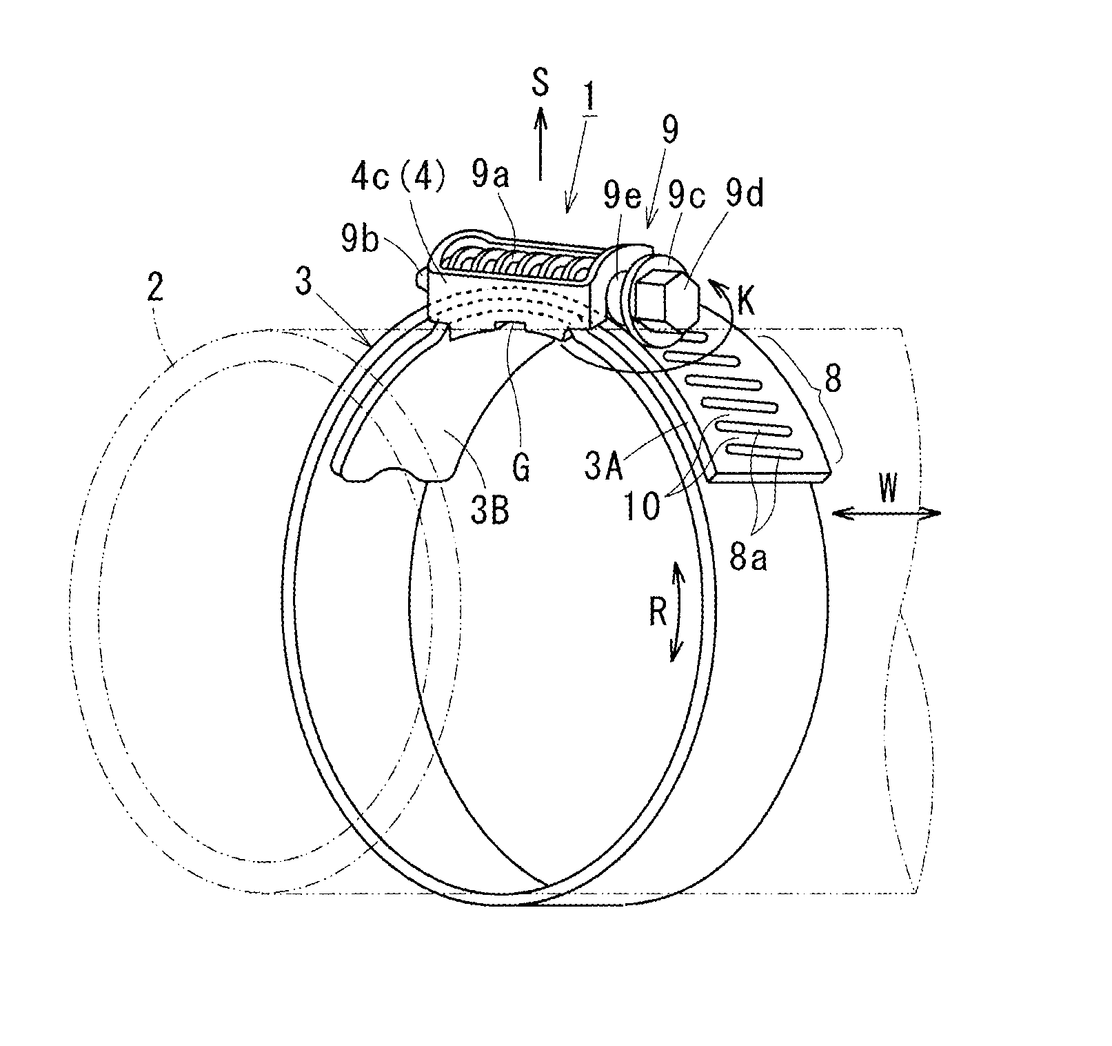
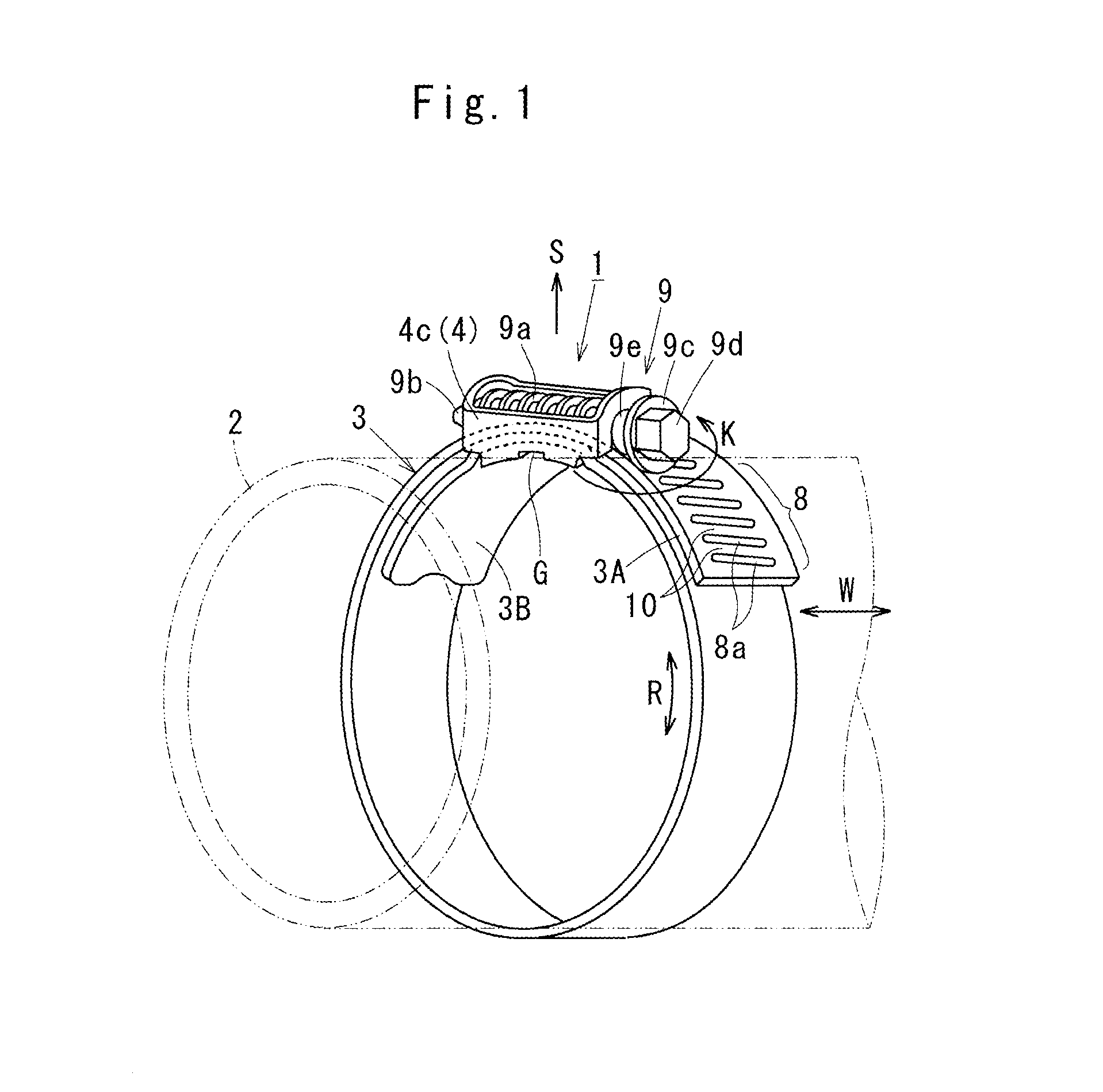
[0052]Referring to FIGS. 1 through 7 which describe a strap-band type connecting device 1 according to the invention. As shown in FIG. 1, the strap-band type connecting device 1 is applied to a connection hose 2 which serves as an article to be wound. The connection hose 2 is made of, for example, a hardened rubber or fiber-reinforced rubber to enhance the mechanical strength by considering durability or endurance recently required for the connection hose 2.

[0053]For this reason, the strap-band type connecting device 1 is improved to well suit for cases in which the connection hose 2 requires a greater amount of winding force (surface pressure) working as a binding force for the connection hose 2.

[0054]By way of illustration, in an internal combustion engine equipped with a turbo-charger (not shown), an intercooler device is used to cool an intaken air compressed to enhance an air-compression ratio. The strap-band type connecting device 1 is used to connect the intercooler device to...

second embodiment

[0092]FIG. 8 shows the invention in which a bottomed frame 4h is formed by an elliptical frame portion 4f and an oval bottom base 4g instead of the rectangular configuration.

[0093]Alternatively, a bottomed frame 4i may be made from an octagonal frame portion 4j and an octagonal bottom base 4k in the circumferential direction R of the strap band 3 as shown in FIG. 9. A bottomed frame 4m may be further made from a diamond-shaped frame portion 4n and an octagonal bottom base 4p in the circumferential direction R of the strap band 3 as shown in FIG. 10. A bottomed frame 4s may be still further made from a hexagonal frame portion 4u and a hexagonal bottom base 4v in the circumferential direction R of the strap band 3 as shown in FIG. 11.

[0094]The bottomed frames 4i, 4m, 4s are illustrated as flat-shaped modification form of the second embodiment which effectuates the same advantages as obtained in the first embodiment of the invention.

[0095]FIGS. 12 through 16 show a third embodiment of ...


PUM


Abstract

In a strap-band type connecting device (1), provided is a housing (4) work-hardened and has a bottomed frame (4c) having a frame portion (4b) and a bottom base (4a) in one piece. The housing (4) has a strength and rigidity higher enough to resist a torsional force (K) when a rod screw (9) is rotationally operated. Even when the rod screw (9) is rotationally operated accidentally with a magnitude more than an allowable amount of torque, it is possible for the housing (4) to resist the torsional force (K) with a sufficient strength insured, so as to keep the strap band (3) winding around the connection hose (2) in a favorable condition for an extended period of time.

Description

BACKGROUND OF THE INVENTION[0001]1. Field of the Invention[0002]The present invention relates to a strap-band type connecting device which has a strap band provided to wind around a connecting portion between a tubular element and a metallic pipe with a predetermined winding force, and particularly concerns to a strap-band type connecting device in which a rod screw is rotatably provided within a housing.[0003]2. Description of Prior Art[0004]A strap-band type connecting device has a strap band provided to wind around a connector hose which serves as an article to be wound. In recent years, the connector hose has been used to vehicular air-conditioners which compress liquid refrigerant with high pressure. The connector hose also has been used to vehicular turbo-chargers which are exposed to high pressure with high ambient temperature. In order to cope with those adverse environments in which the connector hose is installed, high endurance properties have been required for the connec...

Claims


Application Information

Patent Timeline
IPC IPC(8): F16L33/08
CPCF16L33/08F16L33/00Y10T24/1427Y10T24/1431Y10T24/1441Y10T24/44239Y10T24/44248F16B2/08F16L21/08F16L33/02
Inventor TAKAGI, RYUICHIKIMURA, SHIGENOBU
Owner SOGYO
Why Eureka
Try Eureka