
Shutter Valve for Pressure Regulation

a technology of pressure regulation and shutter valve, which is applied in the direction of fluid pressure control, process and machine control, instruments, etc., can solve the problems of inability, inability to design freedom, and inability, and achieve the effect of reducing weight and space, facilitating operation, and increasing overall engine efficiency

Inactive Publication Date: 2014-05-08
CLARKE IND ENG INC
View PDF20 Cites 17 Cited by
  • Summary
  • Abstract
  • Description
  • Claims
  • Application Information

AI Technical Summary

Benefits of technology

The present invention is a pressure regulation valve system that is designed to address the problems in the art by using an electronically controlled valve system without mechanical components to drive the valves. The valves in the system are designed to be unobstructed, allowing for improved fluid flow without disturbing the momentum of the fluid. The system also includes an activation assembly for selectively orientating each valve and determining the precise adjustment of the size of the central aperture for maximum efficiency. The technical effects of the invention include improved machine efficiency, reduced noise, and improved performance and efficiency of pressure regulation systems.

Problems solved by technology

However, and as has been referred to previously herein, the conventional use inferior valves creates a disturbance in the momentum of the working fluid by providing a direct obstruction in the path of fluid flow.
In comparison with Shutter Valves, current valve configurations do not offer the low weight, compactness, unobstructed flow path, pressure chamber design freedom, the ability to operate electronically and controlled by software logic, or infinite aperture adjustability.

Method used


Image

  • Shutter Valve for Pressure Regulation
  • Shutter Valve for Pressure Regulation
  • Shutter Valve for Pressure Regulation

Examples


Embodiment Construction

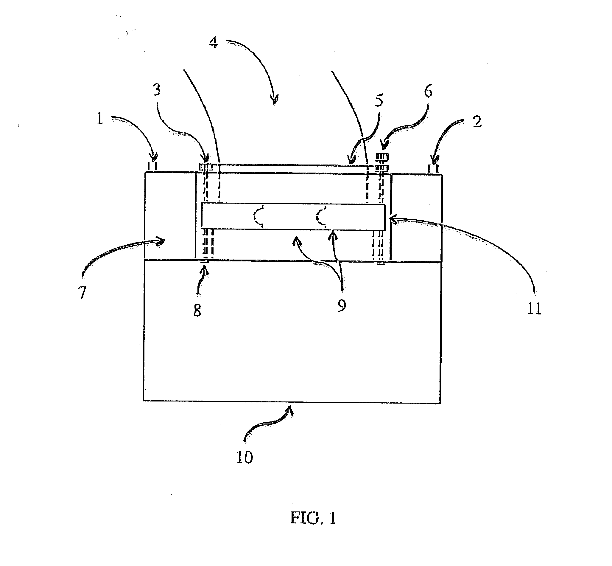
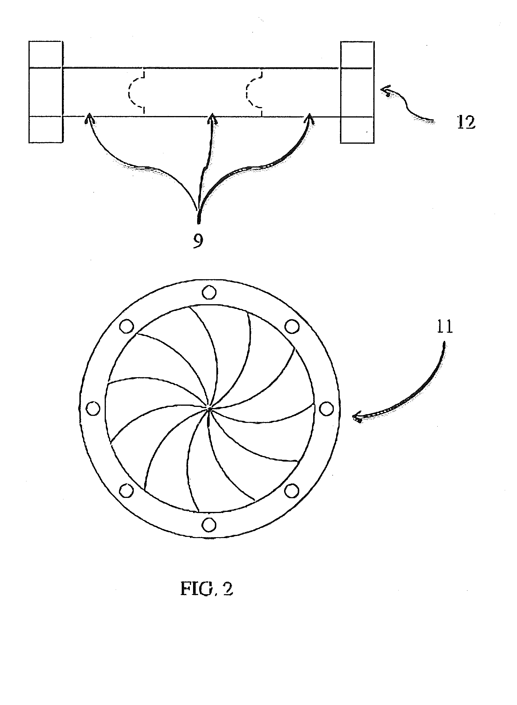
[0043]As shown in the accompany drawings, the present invention is directed towards a valve system incorporating at least one Shutter Valve, as indicated generally by reference numeral 11. With initial reference to FIG. 1, the valve system of the present invention is part of a pressure regulation machine, wherein a pipe 4 is attached to the shutter valve 11 to regulate the pressure of the pressurized vessel 10. The shutter valve is operated mechanically in this representation by a gear belt 5, which is attached to blade gear 3, and selectively operated by cam gear 6. The blade gear 3 and cam gear 6 are attached to the shutter valve 11 by the hinge pin 8. The interlocking shutter blades 9 are operated by the above mentioned valve drive assembly and are lubricated by the lubricant contained within the housing 7, in which the lubricant is fed to the system by the inlet port 1, circulated around the retracting interlocking shutter blades 9, the lubricant being removed to a separate tank...


PUM


Abstract

A valve system designed to regulate the flow of fluids for pressure regulation systems. The valve is defined by a plurality of valve elements in the form of overlapping and interlocking valve blades that can retract and close on command, and defining a central aperture having an adjustable dimension dependent upon the relative positioning of the plurality of valve elements as they are selectively oriented between an open and closed position. The central aperture at least partially defines a free, unobstructed flow path of fluid in pressure regulation applications. The valve system can be driven mechanically or electronically. A mechanical valve control assembly can be comprised of any combination of components that facilitate the operation of said assembly. An electronic control assembly ideally comprises a plurality of sensors each transferring sensor signals to a central processing unit and Shutter Valve driver assembly for purposes of controlling the operation of the pressure regulation system. The central processing unit is interconnected by an activation assembly to the valves so as to regulate the pressure of the system, based on the operational requirements of the pressure regulation system.

Description

BACKGROUND OF THE INVENTION[0001]1. Field of the Invention[0002]Pressure is the force per unit area applied to an object in a direction perpendicular to the surface. As machines that use pressurized fluid that require regulation have become ubiquitous in today's society, the need to have high performance, low cost and reliable pressure regulation valves is essential. Many pressure regulation valves are variations on themes created many hundreds of years ago, and as such, typically operate with deficiencies in performance and operational life in comparison with Shutter Valves. Shutter Valves are entirely different from any valve ever created and offer unparalleled performance, life and cost effectivity.[0003]Applications[0004]A pressure regulator is a valve that cuts off the flow of a liquid or gas that flows with a certain amount of pressure. Regulators are used to allow high-pressure fluid supply lines or tanks to be operated at safe and / or usable pressures for various applications...

Claims


Application Information

Patent Timeline
IPC IPC(8): G05D16/00
CPCG05D16/00F16K3/03Y10T137/7793
Inventor DANIELS, KYLE PATRICK
Owner CLARKE IND ENG INC
Learn More