Ground-based heat sink facilitating electronic system cooling

Inactive Publication Date: 2014-05-08
IBM CORP
View PDF1 Cites 13 Cited by
  • Summary
  • Abstract
  • Description
  • Claims
  • Application Information

AI Technical Summary

Benefits of technology

[0003]In one aspect, the shortcomings of the prior art are overcome and additional advantages are provided through a method which includes: providing a ground-based heat sink controllably coupled to a coolant loop, the ground-based heat sink being at least partially buried in the ground and being configured to transfer heat from coolant passing therethrough into the ground; providing a coolant-to-air heat rejection unit controllab

Problems solved by technology

This heat should be removed from the devices in order to maintain device junction temperatures within desirable limits, with failure to remove heat effectively resulting in increased device temperatures, and potentially leading to thermal runaway conditions.
For example, power dissipation, and therefore heat production, increases as device opera

Method used


Image

  • Ground-based heat sink facilitating electronic system cooling
  • Ground-based heat sink facilitating electronic system cooling
  • Ground-based heat sink facilitating electronic system cooling

Examples


Example

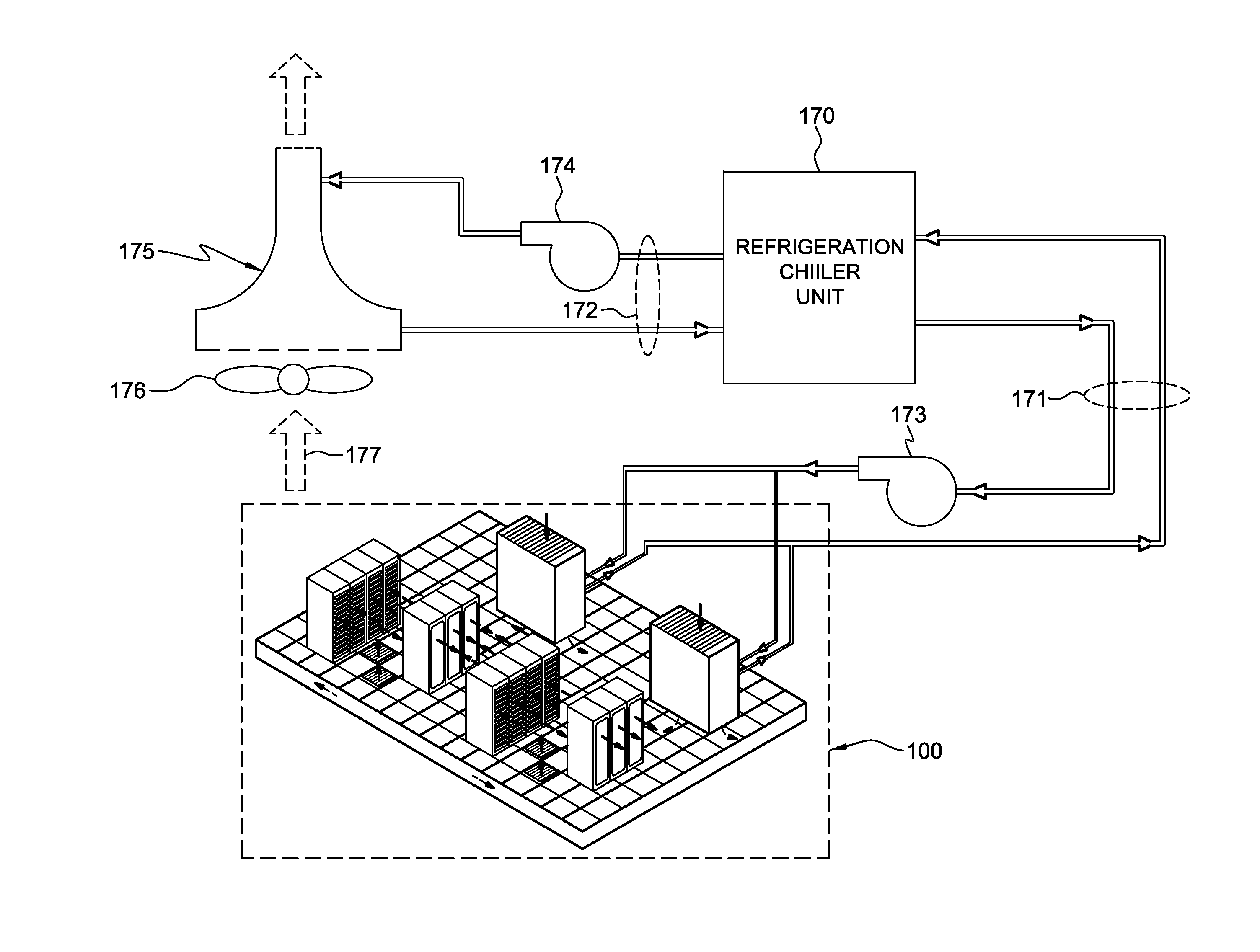
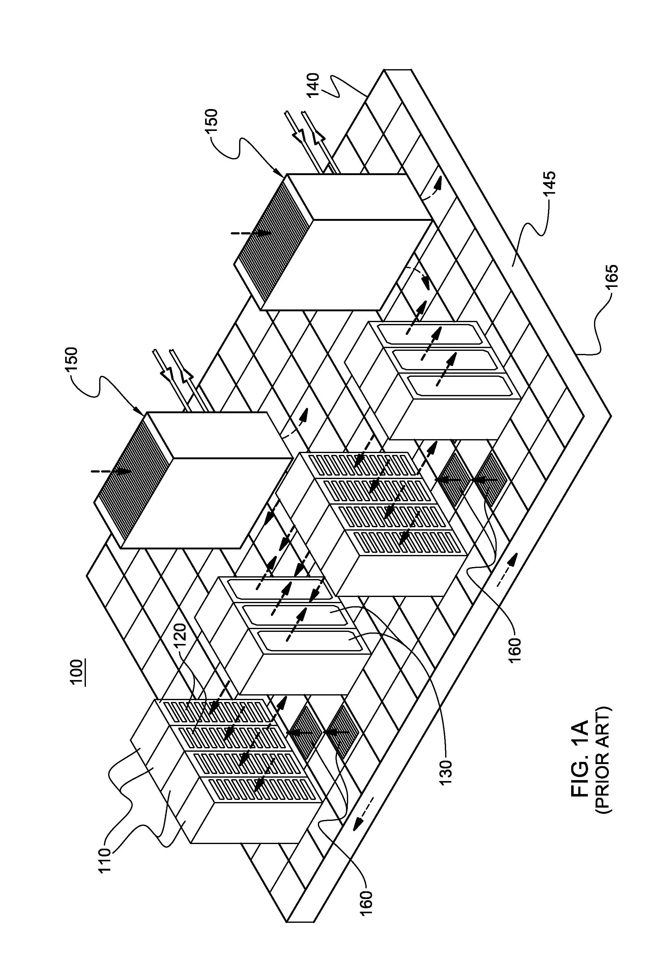
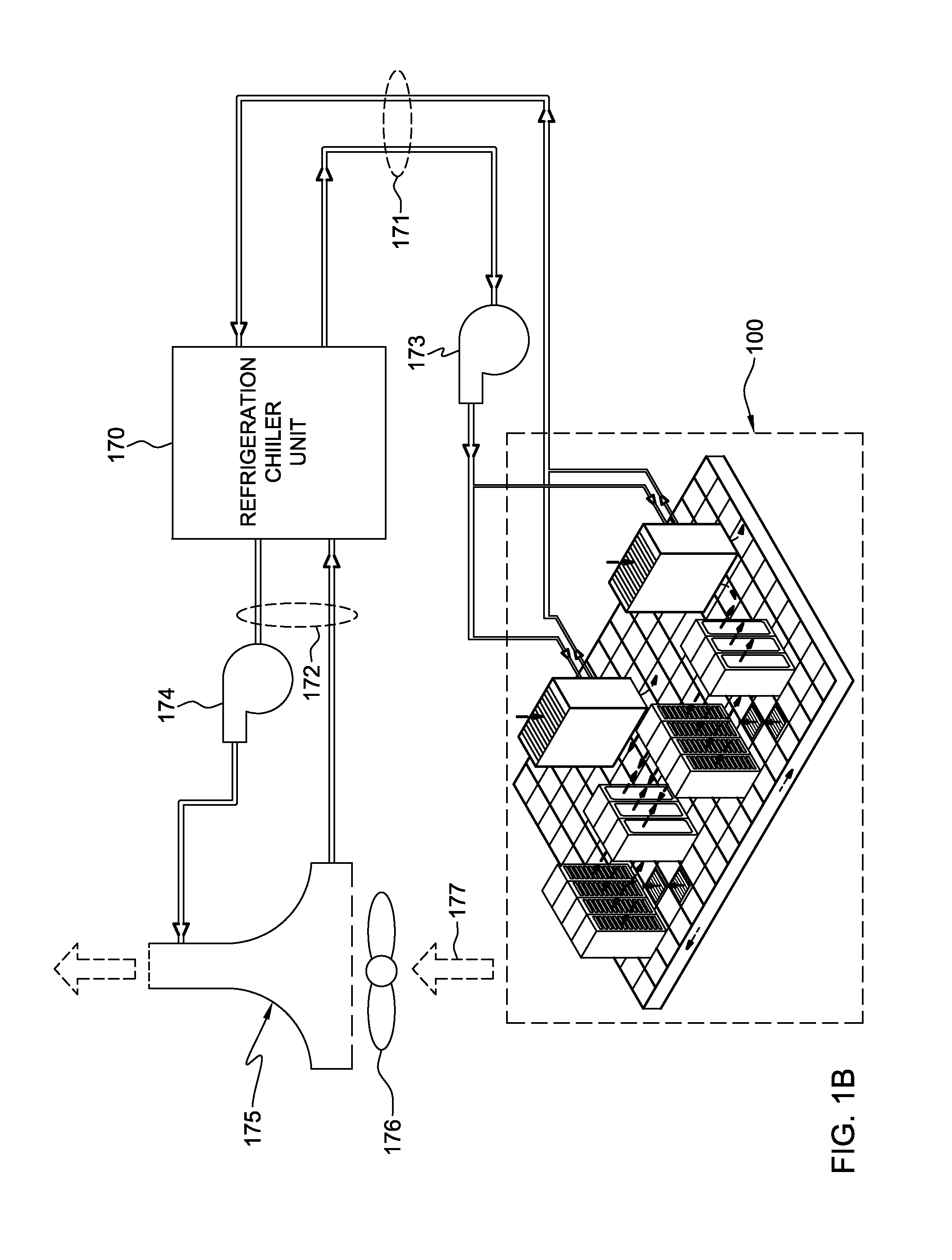
[0027]As used herein, the terms “electronics rack”, and “rack unit” are used interchangeably, and unless otherwise specified include any housing, frame, rack, compartment, blade server system, etc., having one or more heat-generating components of a computer system or electronic system, and may be, for example, a stand-alone computer processor having high, mid or low end processing capability. In one embodiment, an electronics rack may comprise a portion of an electronic system, a single electronic system or multiple electronic systems, for example, in one or more sub-housings, blades, books, drawers, nodes, compartments, etc., having one or more heat-generating electronic components disposed therein. An electronic system(s) may be movable or fixed, for example, relative to an electronics rack, with rack-mounted electronic drawers and blades of a blade center system being two examples of electronic systems (or subsystems) of an electronics rack to be cooled.

[0028]“Electronic compone...


PUM


Abstract

Cooling methods are provided which include providing a heat sink having a housing with a compartment, a coolant inlet, and a coolant outlet. The housing is configured for a coolant to flow from the coolant inlet through the compartment to the coolant outlet, wherein the coolant is transferring heat extracted from one or more electronic components. The heat sink further includes one or more heat pipes having a first portion disposed within the compartment of the housing and a second portion disposed outside the housing. The heat pipe(s) is configured to extract heat from the coolant flowing through the compartment, and to transfer the extracted heat to the second portion disposed outside the housing. The second portion outside the housing is disposed to facilitate conducting the extracted heat into the ground.

Description

CROSS-REFERENCE TO RELATED APPLICATION[0001]This application is a continuation of U.S. Ser. No. 13 / 671,829, filed Nov. 8, 2012, and entitled “Ground-Based Heat Sink Facilitating Electronic System Cooling”, and which is hereby incorporated herein by reference in its entirety.BACKGROUND[0002]As is known, operating electronic components, such as electronic devices, produce heat. This heat should be removed from the devices in order to maintain device junction temperatures within desirable limits, with failure to remove heat effectively resulting in increased device temperatures, and potentially leading to thermal runaway conditions. Several trends in the electronics industry have combined to increase the importance of thermal management, including heat removal for electronic devices, including technologies where thermal management has traditionally been less of a concern, such as CMOS. In particular, the need for faster and more densely packed circuits has had a direct impact on the im...

Claims


Application Information

Patent Timeline
IPC IPC(8): H05K7/20
CPCH05K7/2039F24T10/30F24T10/40F28D15/0266F28D15/0275H05K7/20827Y02E10/10
Inventor CAMPBELL, LEVI A.CHU, RICHARD C.DAVID, MILNES P.ELLSWORTH, JR., MICHAEL J.IYENGAR, MADHUSUDAN K.SCHMIDT, ROGER R.SIMONS, ROBERT E.
Owner IBM CORP
Why Eureka
Try Eureka