Cascading Plant

a technology of cascading plants and evaporators, which is applied in the field of refrigeration and air conditioning systems, can solve the problems of high collective damage caused by leveraging emissions, inability to reduce leakage, and rapid degradation of lubricating oil, and achieves reduced mass flow rate, reduced compressor size, and reduced leakage. effect of

Inactive Publication Date: 2014-05-29
CITY HLDG AUS
View PDF5 Cites 2 Cited by
  • Summary
  • Abstract
  • Description
  • Claims
  • Application Information

AI Technical Summary

Benefits of technology

[0032]Even more preferably, the fraction of latent heat available at the evaporator is substantially increased compared to current practice because of a reduction in the condensing temperature and pressure. A consequent benefit is a reduction in mass flow rate of the refrigerant in the lower stage of the cascade plant which inherently necessitates a smaller compressor. The net effect is that not only the compressor size is smaller, but also it works more efficiently resulting substantial reduction in indirect greenhouse gas emissions due to electricity consumption.
[0033]According to another preferred aspect, since the condensing temperature may be lowered, the maximum operating pressure in the lower stage of cascade cycle is also reduced. This causes smaller leakages of refrigerant because the leakage is proportional to the square root of the gauge pressure.

Problems solved by technology

The current Australian refrigeration and air conditioning trade practices are unable to reduce the leakages below 10% of initial charge per year.
While this may not appear much, the amount of supermarkets Australia wide is 1500 and therefore the collective damage caused by their leveraging emissions is high.
The current practice is to use a separate set of compressors that provide low temperature refrigeration which operate between evaporating and condensing temperatures of −30 to 45° C., which is a very large thermal boost that is fraught with very poor volumetric and isentropic efficiencies of the compressors, very high discharge temperatures that led to rapid degradation of the lubricating oil.
Further, because of large differential between the suction and discharge pressures, the leakage losses are large.Because of large thermal boosts, the available latent heat at the evaporator reduces to almost 50%.
Further, independent controls do not allow fine tuning of matching interfaces resulting in high energy consumption for refrigeration.

Method used


Image

  • Cascading Plant
  • Cascading Plant
  • Cascading Plant

Examples


Embodiment Construction

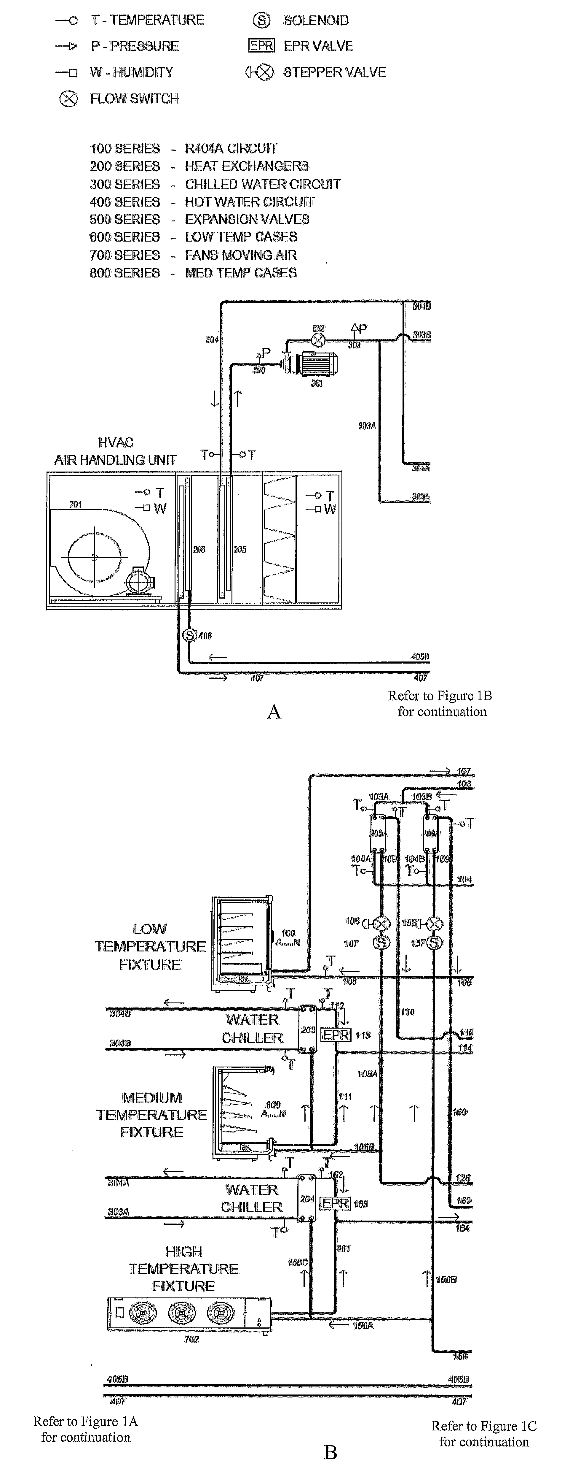
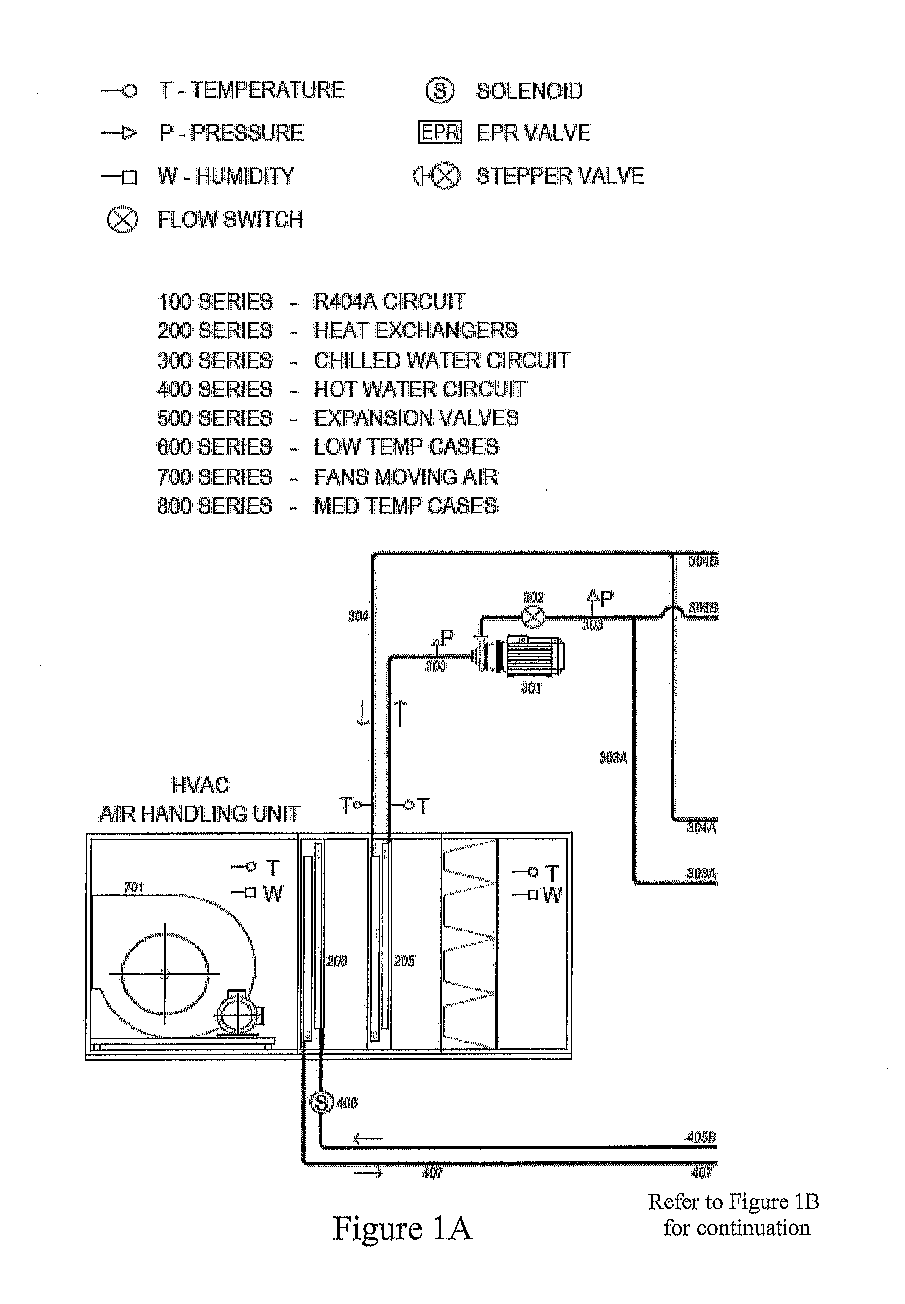
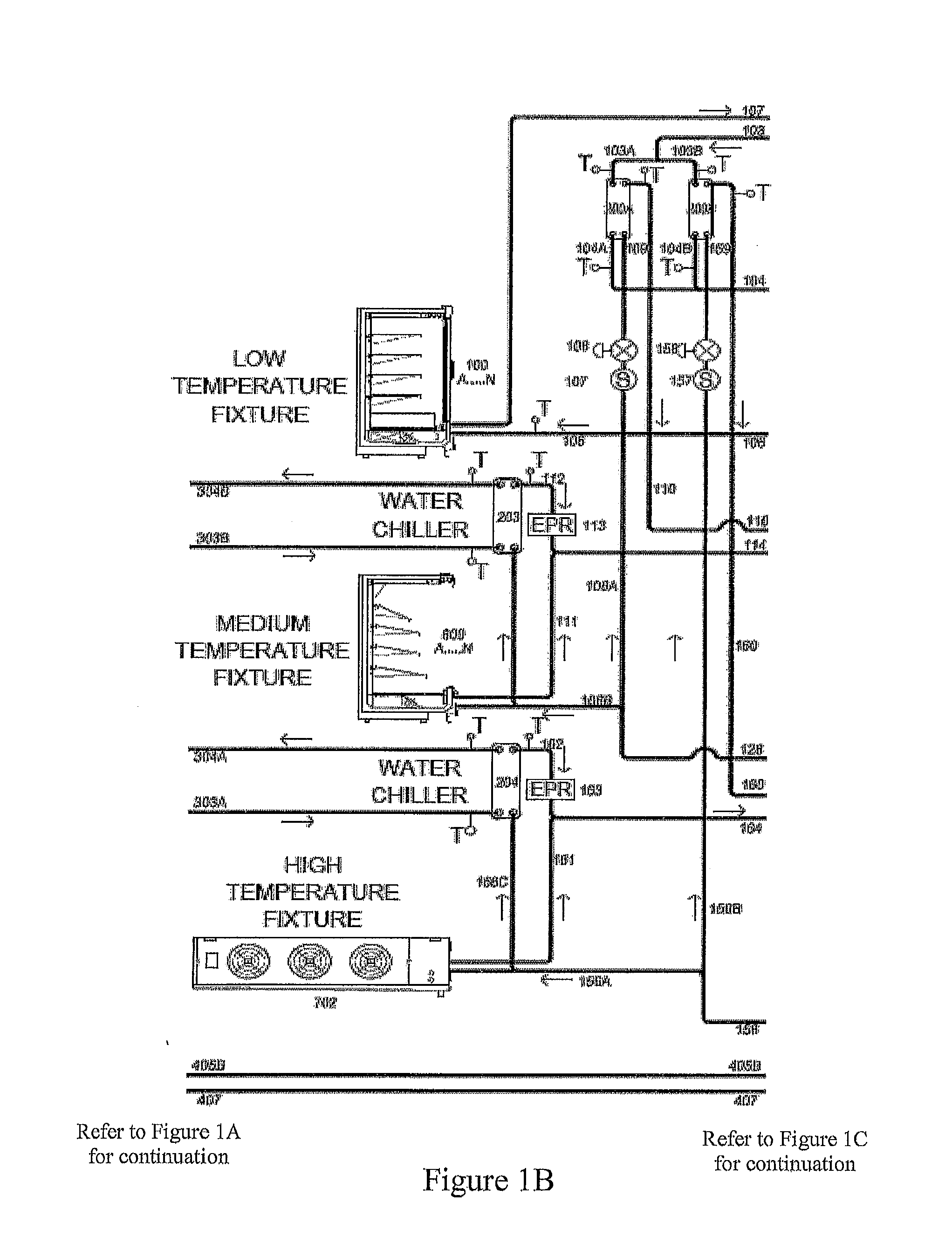
[0038]The invention will now be further illustrated with reference to the non limiting example depicted in the accompanying FIGURE. In this respect the following possibilities exist, all of which are of the inventions disclosed here.

[0039]1. The low and high stage of cascade refrigeration units are used with the same refrigerant 404a or 507a and combine the air conditioning service with the high stage.

[0040]This embodiment eliminates the condenser for the low temperature refrigeration rack. It addressed the concerns of some users who do not want to have two synthetic working fluids on site.

[0041]2. The high stage refrigerant in case 1 above is replaced with a low global warming potential and lower vapour pressure refrigerant such as HFC 134a. This option reduces the direct global warming potential even below that of the option 1 above. The high global warming potential refrigerant is contained within the low stage circuit which caters to much smaller load than the high stage segment...


PUM


Abstract

An integrated refrigeration and air conditioning plant working in a cascade cycle with two different refrigerants for the low and high temperature circuits. The low temperature segment works with an ozone friendly synthetic refrigerant with a minimal amount of refrigerant charge, while the upper stage operates with another ozone friendly refrigerant with much lesser global warming potential than the one in the low stage. The upper and/or medium temperature circuit also services the air conditioning needs of the environment where the refrigerated equipment is located, such as the shop floor of a supermarket or a laboratory housing the cabinets that keep refrigerators.

Description

FIELD OF INVENTION[0001]The invention relates to refrigeration and air conditioning systems, including such systems when used in a supermarket setting. It specifically addresses the lacuna in integrating seemingly different, but intricately related, domains of cooling requirements at various temperature levels. The objectives are sought to be achieved in a manner that is environmentally friendly, energy efficient and operated in an intelligent way that marries the thermodynamic fluid dynamic interface at two different refrigerants.BACKGROUND TO THE PRESENT INVENTION[0002]In this document the numbering of refrigerants is in accordance with the protocol recommended by the learned societies relevant to the profession of refrigeration and air conditioning, such as American Society of Refrigeration, Heating and Air conditioning Engineers (ASHRAE), International Institute of Refrigeration (IIR), Australian Institute of Refrigeration, Air Conditioning and Heating (AIRAH), Japan Society of ...

Claims


Application Information

Patent Timeline
Patent Type & Authority Applications(United States)
IPC IPC(8): F25D13/04
CPCF25B7/00F25B2309/06F25B2339/047F25B2400/22F25D13/04
Inventor CONJEEVARAM, SARATHYVISSER, MICHAELKANDADAI, SRINIVASANSHEAHEN, PAUL
Owner CITY HLDG AUS
Why Eureka
Try Eureka