

Weir For Improved Crystal Growth in A Continuous Czochralski Process
a technology of czochralski process and weir, which is applied in the direction of crystal growth process, polycrystalline material growth, under protective fluid, etc., can solve the problems of high increased replacement cost, and failure to address the problem of rapid erosion rate of weir
- Summary
- Abstract
- Description
- Claims
- Application Information
AI Technical Summary
Benefits of technology
Problems solved by technology
Method used
Image

Examples
Embodiment Construction
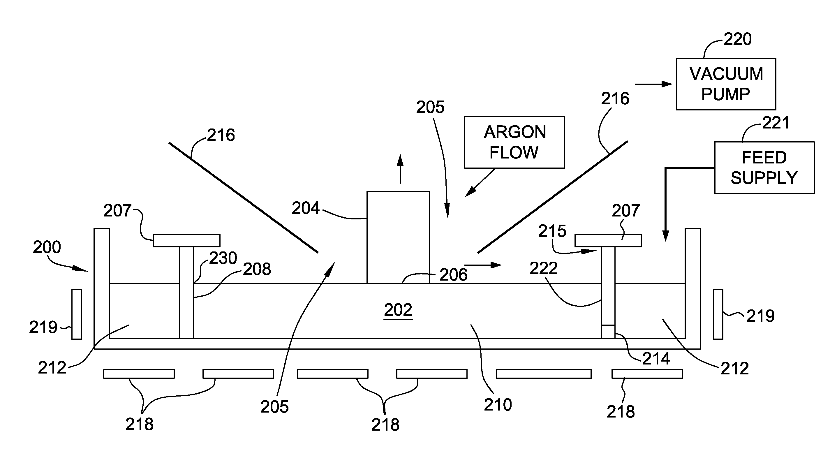
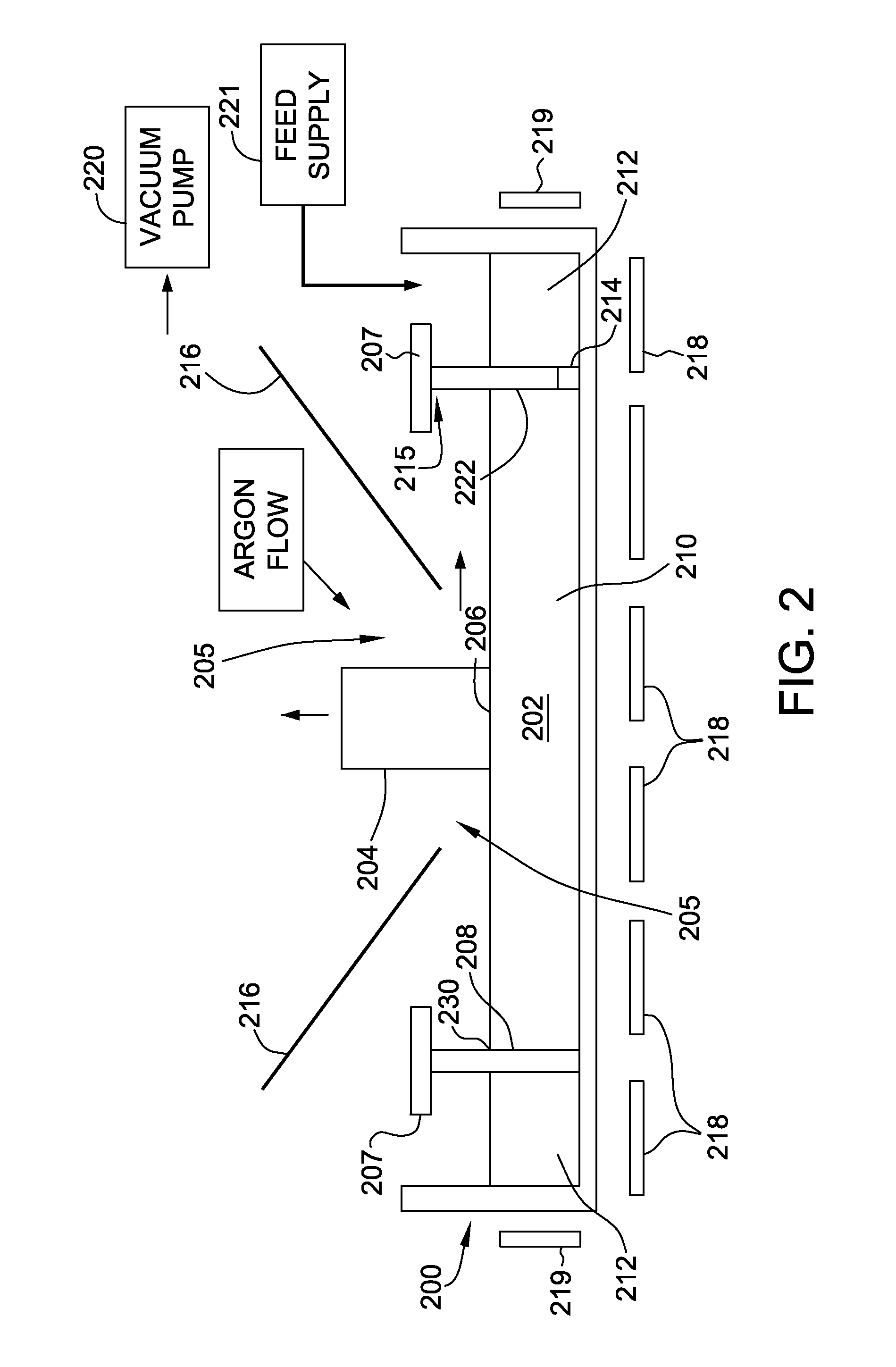
[0018]Referring to FIG. 2, in accordance with an embodiment of the disclosure, a cap weir 208 is provided in a crucible 200. The cap weir 208 has generally a cylindrical shape with vertically extending sidewalls 222 mounted at the bottom of the crucible 200 that define a growth region in silicon melt 202. The growth region 210 in silicon melt 202 is defined as the region encompassed by sidewalls 222 (i.e., radially inward of the sidewalls). An outer feed supplement region 212 is defined as a region outside of the sidewalls 222 (i.e., radially outward of the sidewalls). As such, the cap weir 208 separates the growth region 210 from a first region or melt supplement region 212 to isolate and prevent thermal and mechanical disturbances from affecting the growing crystal in the growth region 210.
[0019]In some embodiments a passageway 214 is defined in sidewalls 222 for controlling melt flow between the melt supplement region 212 and growth region 210. A feed supply 221 supplies a source...
PUM
| Property | Measurement | Unit |
|---|---|---|
| height | aaaaa | aaaaa |
| partial pressure | aaaaa | aaaaa |
| pressure | aaaaa | aaaaa |
Abstract
Description
Claims
Application Information