Elastic wave device

a technology of elastic wave and device, applied in piezoelectric/electrostrictive/magnetostrictive devices, piezoelectric/electrostriction/magnetostriction machines, electrical apparatus, etc., can solve the problems of limited increase of fractional bandwidth, or bandwidth ratio, and achieve large bandwidth ratio and effective increase of the electromechanical coupling coefficient of sh plate waves.

Active Publication Date: 2014-05-29
MURATA MFG CO LTD
View PDF4 Cites 78 Cited by
  • Summary
  • Abstract
  • Description
  • Claims
  • Application Information

AI Technical Summary

Benefits of technology

[0023]In an elastic wave device according to various preferred embodiments of the present invention, θ of the Euler angles of LiNbO3 is within the above specific range and the thickness of a LiNbO3 substrate

Problems solved by technology

A configuration using the SH plate wave described in Japanese Unexamined Patent Application Publication No. 2002-152007 cannot necessarily achieve

Method used


Image

  • Elastic wave device
  • Elastic wave device
  • Elastic wave device

Examples


Embodiment Construction

[0041]Preferred embodiments of the present invention will now be described in detail with reference to the accompanying drawings such that the present invention will become apparent.

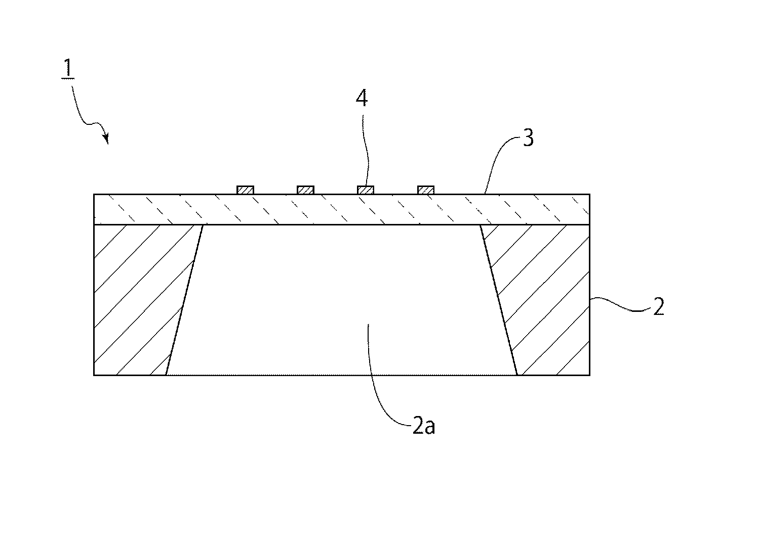
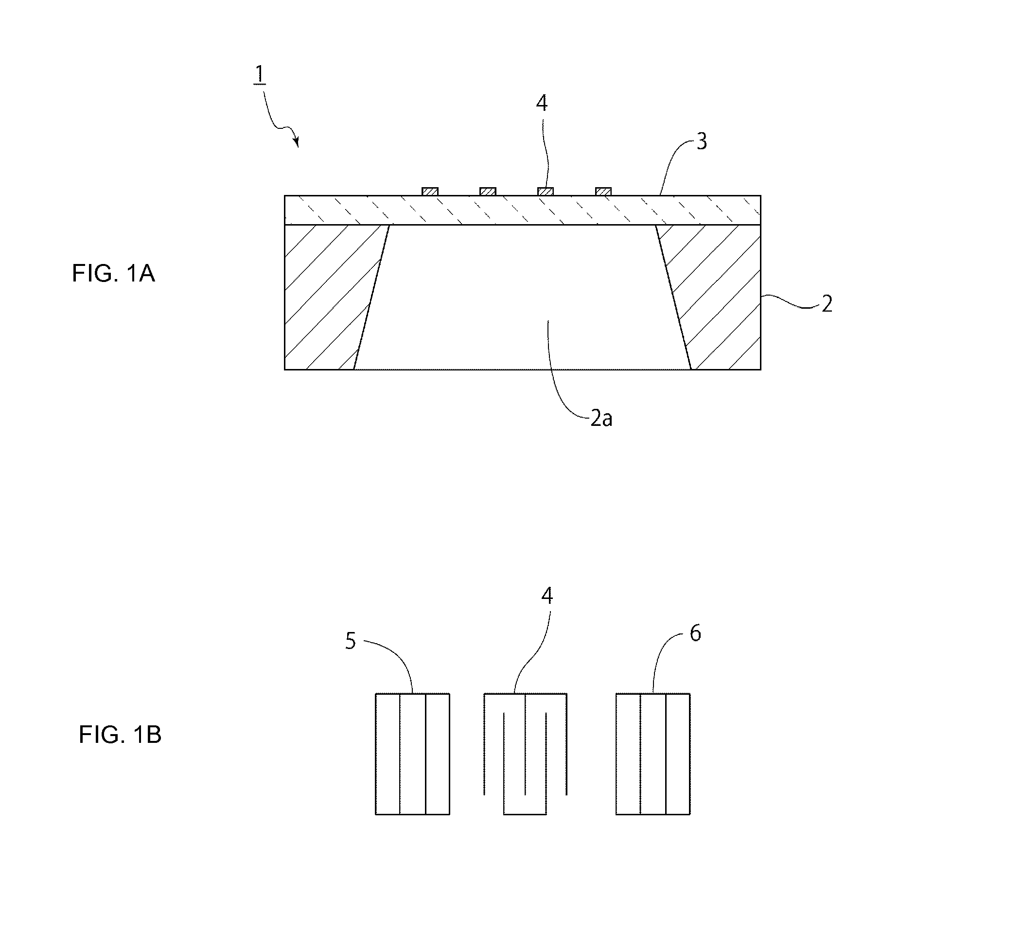
[0042]FIG. 1A is a front sectional view of an elastic wave device according to a first preferred embodiment of the present invention and FIG. 1B is a schematic plan view illustrating the electrode structure of the elastic wave device.

[0043]The elastic wave device 1 of this preferred embodiment includes a support 2. The support 2 is made of an appropriate rigid material such as Si, an insulating ceramic, or metal. The support 2 is overlaid with a LiNbO3 substrate 3. The thickness of the LiNbO3 substrate 3 preferably ranges from about 0.05, to about 0.25λ, for example. The support 2 includes a through-hole 2a. In a region facing the through-hole 2a, IDT electrodes 4 are located on the upper surface of the LiNbO3 substrate 3.

[0044]FIG. 1A schematically shows a portion provided with the IDT electrodes 4. In ...


PUM


Abstract

An elastic wave device making use of an SH plate wave propagating in LiNbO3 substrates includes a LiNbO3 substrate, IDT electrodes located on at least one surface of the LiNbO3 substrate, and a support which is bonded to the LiNbO3 substrate such that the support is located outside a region provided with the IDT electrodes and supports the LiNbO3 substrate, wherein θ of the Euler angles (0°, θ, 0°) of the LiNbO3 substrate ranges from about 92° to about 138° and the thickness of the LiNbO3 substrate ranges from about 0.05λ to about 0.25λ, where λ is the wavelength determined by the pitch between electrode fingers of the IDT electrodes.

Description

BACKGROUND OF THE INVENTION[0001]1. Field of the Invention[0002]The present invention relates to elastic wave devices used as resonators or band-pass filters and particularly relates to an elastic wave device making use of an SH plate wave propagating in LiNbO3 substrates.[0003]2. Description of the Related Art[0004]Hitherto, various elastic wave devices making use of a plate wave propagating in LiNbO3 have been proposed. For example, Japanese Unexamined Patent Application Publication No. 2002-152007 below discloses an elastic wave resonator shown in FIG. 16. The elastic wave resonator 1001 includes a LiNbO3 single-crystalline substrate 1002 as shown in FIG. 16. The center of the LiNbO3 single-crystalline substrate 1002 is a thin plate portion 1002a. That is, a central portion of the LiNbO3 single-crystalline substrate 1002 is thin and has a thickness h. In an example described in Japanese Unexamined Patent Application Publication No. 2002-152007, the thickness h is 0.03λ0.[0005]The...

Claims


Application Information

Patent Timeline
IPC IPC(8): H03H9/02H03H9/25
CPCH03H9/02228H03H9/174H03H9/02015H03H9/02559H03H9/02992H03H9/25
Inventor KADOTA, MICHIO
Owner MURATA MFG CO LTD
Why Eureka
Try Eureka