Magnetic core, method and device for its production and use of such a magnetic core

a technology of magnetic core and magnetic core, which is applied in the direction of magnetic core/yokes, transformers/inductances, magnetic materials, etc., can solve the problems of large design, large losses, and large design, and achieve the effect of small losses

Inactive Publication Date: 2014-06-05
VACUUMSCHMELZE GMBH & CO KG
View PDF3 Cites 22 Cited by
  • Summary
  • Abstract
  • Description
  • Claims
  • Application Information

AI Technical Summary

Benefits of technology

[0008]There remains a need to eliminate the drawbacks according to the state of the art. In particular, this need is satisfied by a magnetic core as disclosed herein which allows the production of interphase transformers that have small losses at operating frequencies of up to 10 kHz or more, tolerate peak currents of more than 100 A without becoming saturated, and can be operated at temperatures of up to 200° C.

Problems solved by technology

In this case, they are usually designed with flattened FeSi cores, which results in relatively heavy and large designs.
The latter is disadvantageous for certain applications, such as, for example, in aeronautics, where a design that is as lightweight as possible is required.
With the increase in frequency, however, losses also increase.
There, it is also explained that the heating of the interphase transformer poses a problem because of the power loss and cooling of the device.
It is not possible to use common interphase transformers in engine controllers in aircraft, since they would become much too hot due to the increased operating frequencies.
This results in a five- to ten-fold increase in weight of the cores that are used.

Method used


Image

  • Magnetic core, method and device for its production and use of such a magnetic core
  • Magnetic core, method and device for its production and use of such a magnetic core
  • Magnetic core, method and device for its production and use of such a magnetic core

Examples


Embodiment Construction

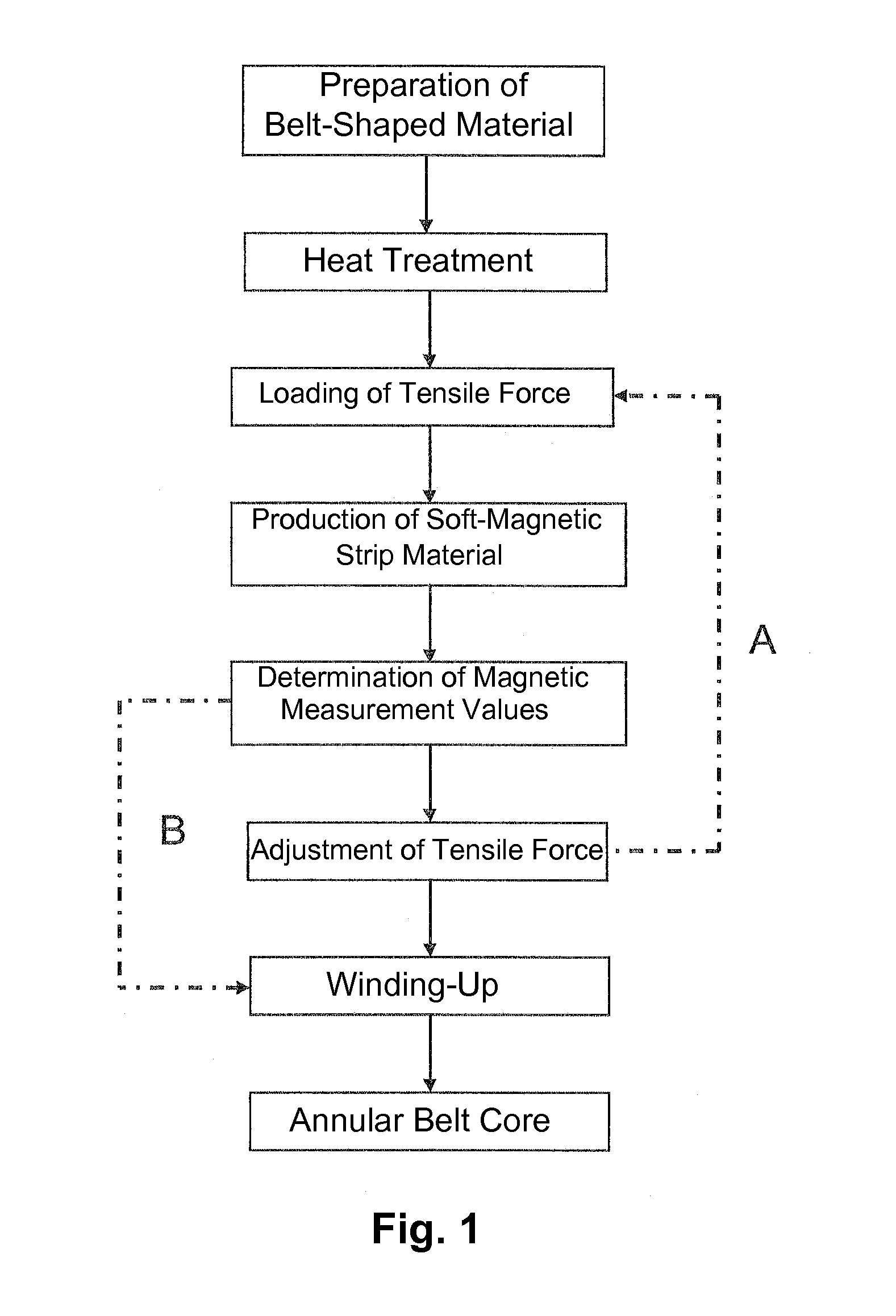
[0116]FIG. 1 diagrammatically shows an exemplary course of the improved method for the production of improved magnetic cores in the form of annular belt cores. The method comprises the preparation of a belt-shaped material, the heat treatment of the belt-shaped material at a heat-treatment temperature, and the loading of the heat-treated belt-shaped material with a tensile force in a longitudinal direction of the belt-shaped material in order to produce a tensile stress in the belt-shaped material. These steps are used to produce the soft-magnetic strip material from the belt-shaped material. In addition, the method comprises a determination of at least one magnetic measurement value of the soft-magnetic strip material produced and an adjustment of the tensile force for setting the tensile stress in reaction to the determined magnetic measurement value (arrow A). Also, the method comprises one step of winding up at least one defined section of the soft-magnetic strip material being ...


PUM

PropertyMeasurementUnit
tensile stressaaaaaaaaaa
temperatureaaaaaaaaaa

Abstract

A magnetic core, such as for an interphase transformer, made of a nanocrystalline alloy, which consists of
Fe100-a-b-c-d-x-y-zCuaNbbMcTdSixByZz and up to 1 at. % of impurities, whereby M is one or more of the elements Mo, Ta or Zr; T is one or more of the elements V, Cr, Co or Ni; and Z is one or more of the elements C, P or Ge, and
    • 0 at. %≦a<1.5 at. %,
    • 0 at. %≦b<4 at. %,
    • 0 at. %≦c<4 at. %,
    • 0 at. %≦d<5 at. %,
    • 12 at. %<x<18 at. %,
    • 5 at. %<y<12 at. %, and
    • 0 at. %≦z<2 at. %,
the core having a saturation magnetostriction of <2 ppm and a permeability between 100 and 1,500, wherein the alloy has been exposed to a heat treatment at a temperature between 450 and 750° C. under a tensile stress between 30 and 500 MPa.

Description

[0001]This application claims benefit under 35 U.S.C. §119 of the filing date of German patent application DE 10 2012 218 657.3, filed Oct. 12, 2012, the entire contents of which is incorporated herein by reference for all purposes.BACKGROUND[0002]1. Field[0003]Disclosed herein is a magnetic core, in particular for an interphase reactor, a method and a device for the production of such a magnetic core, and a method of use of such a magnetic core.[0004]2. Description of the Related Art[0005]Interphase reactors, which are also referred to as interphase transformers, are traditionally used in low-frequency ac technology (for example, 50 Hz technology) for coupling multipolar rectifiers. In this case, they are usually designed with flattened FeSi cores, which results in relatively heavy and large designs. The latter is disadvantageous for certain applications, such as, for example, in aeronautics, where a design that is as lightweight as possible is required. One way to save weight and ...

Claims


Application Information

Patent Timeline
Patent Type & Authority Applications(United States)
IPC IPC(8): H01F1/40
CPCH01F1/40H01F3/04C22C33/003C22C38/002C22C38/02C22C38/12C22C38/16C22C45/02C22C45/04H01F1/15308H01F1/15333H01F41/0226
Inventor HERZER, GISELHERPOLAK, CHRISTIANREICHERT, KLAUS
Owner VACUUMSCHMELZE GMBH & CO KG
Why Eureka
Try Eureka