
Control device of internal-combustion engine

Inactive Publication Date: 2014-06-12
TOYOTA JIDOSHA KK
View PDF2 Cites 6 Cited by
  • Summary
  • Abstract
  • Description
  • Claims
  • Application Information

AI Technical Summary

Benefits of technology

The present invention provides a control device for an internal-combustion engine that can improve combustion quality by using an intermediate product that is generated from unburnt alcohol in alcohol-blended fuel. This intermediate product has a high latent heat and is unstable, which makes it easy to oxidize and burn, resulting in improved combustion quality and performance of the engine. The control device detects the intermediate product and uses it to control the engine in a way that improves combustion quality.

Problems solved by technology

By the way, since the latent heat for evaporation of alcohol in alcohol-blended fuel is high, especially on low-temperature starting, evaporation thereof is not promoted and unburnt gas containing aldehyde which is an unstable intermediate product due to its chemical structure, etc. are likely to generate.
On the other hand, since an intermediate product thus generated is un stable due to its chemical structure, it has the characteristic that it is likely to be oxidized, i.e., it is easily burned.

Method used


Image

  • Control device of internal-combustion engine
  • Control device of internal-combustion engine
  • Control device of internal-combustion engine

Examples


first embodiment

a. First embodiment

[0036]Hereafter, a control device of an internal-combustion engine according to the first embodiment of the present invention (hereinafter, may be simply referred to as “the present device”) will be explained referring to drawings.

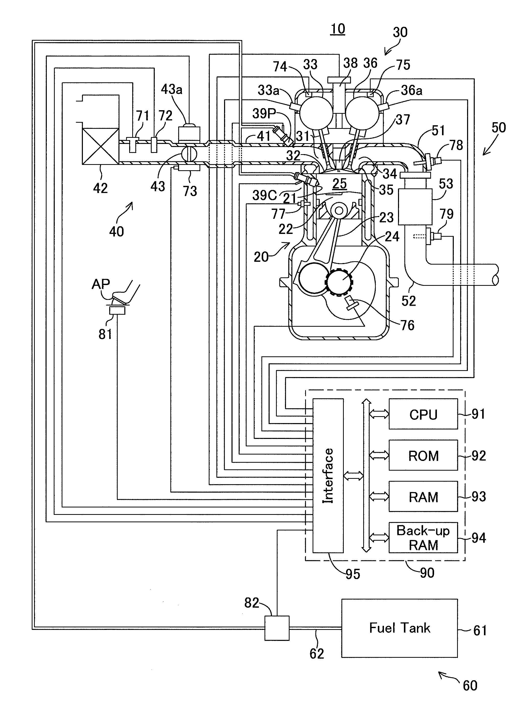
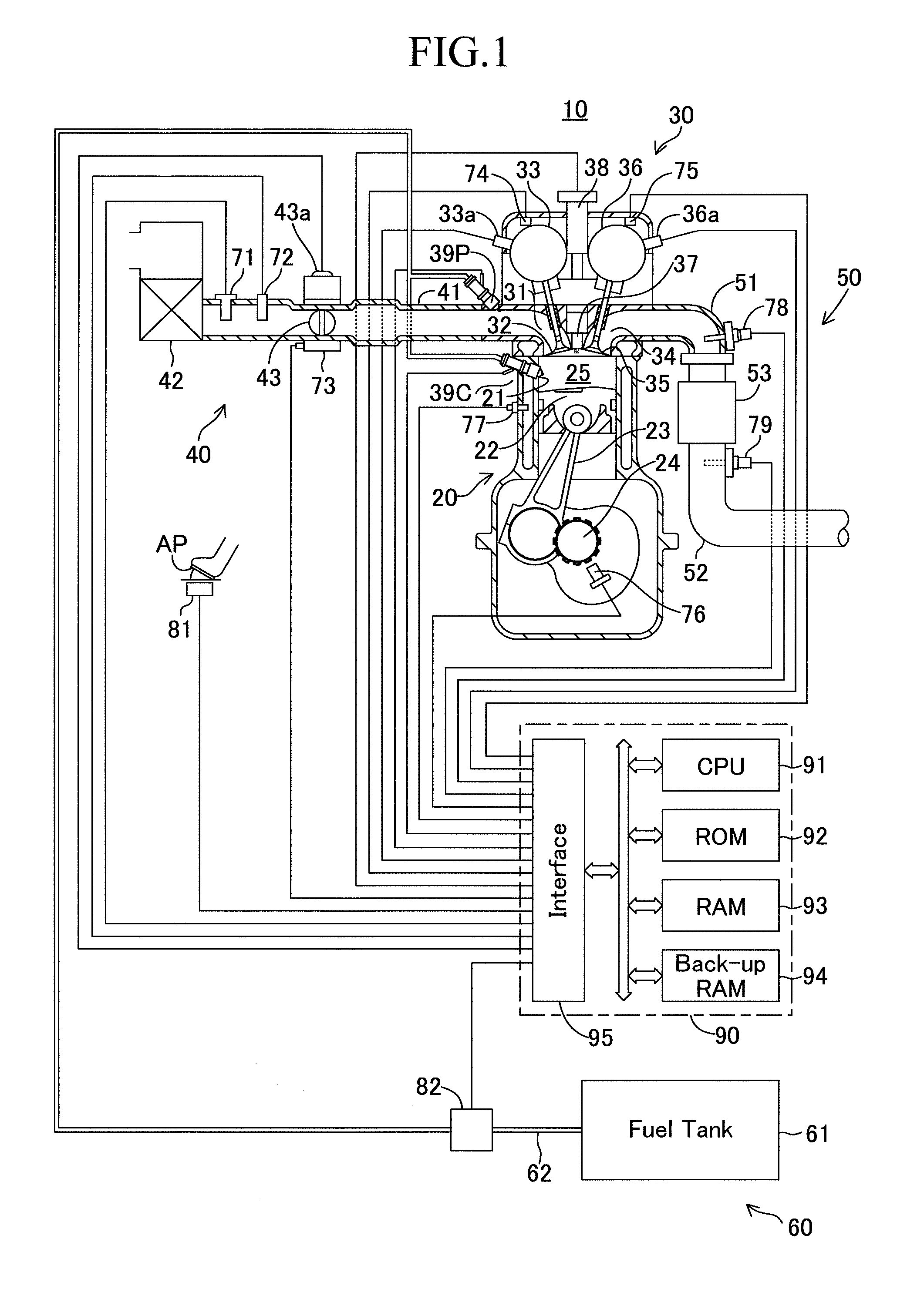
[0037]FIG. 1 shows the schematic configuration of a system wherein the present device is applied to a four-cycle spark-ignited multicylindered (in-line four-cylinder) internal-combustion engine 10. In addition, although FIG. 1 shows only the section of a specific cylinder, other cylinders also has the same configuration.

[0038]This internal-combustion engine 10 is equipped with a cylinder block part 20 containing a cylinder block, a cylinder block lower case, oil pan, etc., a cylinder head part 30 fixed on the cylinder block part 20, an intake system 40 for supplying air-fuel mixture of alcohol-blended fuel to the cylinder block part 20, an exhaust system 50 for emitting exhaust gas from the cylinder block part 20 outside, and a fuel syst...

second embodiment

b. Second Embodiment

[0103]In the above-mentioned first embodiment, the present device is applied to the internal-combustion engine 10 equipped with the dual injection system which has the port injection valve 39P and the cylinder injection valve 39C and carried out. In this case, although an anew illustration is omitted, it is also possible to carry out with the application of the present device to the internal-combustion engine 10 which has the port injection valve 39P shown in FIG. 1 omitted and is equipped only with the cylinder injection valve 39C at least. Although this second embodiment will be explained hereafter, since it differs in that the port injection valve 39P is omitted as compared with the configuration of the above-mentioned first embodiment, the same mark will be assigned to the same portion as the above-mentioned first embodiment, and explanation of configuration and the same operation will be omitted.

[0104]In this second embodiment, the internal-combustion engine...


PUM


Abstract

When alcohol-blended fuel is supplied to an internal-combustion engine, the magnitude of alcohol concentration (more particularly, ethanol concentration Cetha) is judged (Step 1005) and, based on this judgment, the magnitude of operational status temperature (more particularly, cooling water temperature THW) is judged (Step 1015). Then, when the alcohol concentration is large and the operational status temperature is low, generation of an intermediate product which is an oxide of alcohol contained in the alcohol-blended fuel in an unburnt state after main injection and alcohol contained in the alcohol-blended fuel in an unburnt state after post injection (more particularly, aldehyde) is promoted, and the generated intermediate product is trapped in an intake passage by making an intake valve into an opened state in an exhaust stroke of the internal-combustion engine (Step 1055).

Description

TECHNICAL FIELD [0001]The present invention relates to a control device of an internal-combustion engine which controls an internal-combustion engine. Hereinafter, an internal-combustion engine may be simply referred to as an “engine”.BACKGROUND ART [0002]Conventionally, a control device of an internal-combustion engine which carries out feedback control of the air / fuel ratio of the air-fuel mixture supplied to an engine (hereinafter, may be simply referred to as an “air / fuel ratio of an engine”) based on each output value of an upper stream side air / fuel ratio sensor and a lower stream side air / fuel ratio sensor disposed on the upper stream side and the lower stream side, respectively, from a three-way catalyst (hereinafter, may be simply referred to as a “catalyst”) in an exhaust passage of an internal-combustion engine is known widely. In such a control device, the upper stream side air / fuel ratio sensor and the lower stream side air / fuel ratio sensor detect the air / fuel ratio of...

Claims


Application Information

Patent Timeline
IPC IPC(8): F02B17/00
CPCF02D19/0692Y02T10/26F02D41/405F02D13/0207F02B17/005F02D41/0025F02D19/0689F02D35/02F02D41/025F02D2041/001F02D19/088F02D13/0219F02D19/084F02D2200/0611Y02T10/18Y02T10/44Y02T10/47F02D41/006Y02T10/36F02D41/3094F02D41/064Y02T10/12Y02T10/30Y02T10/40
Inventor MATSUDA, KAZUHISAMORITA, KOUJITSUKAGOSHI, TAKAHIRO
Owner TOYOTA JIDOSHA KK
Learn More