Water Supply Systems

Inactive Publication Date: 2014-06-12
LANDROK MADS
View PDF8 Cites 11 Cited by
  • Summary
  • Abstract
  • Description
  • Claims
  • Application Information

AI Technical Summary

Benefits of technology

The present invention is related to a water supply system that uses natural heat and humid air to evaporate water and cool it down again at a different location. The system includes an evaporation station and a condensation station, which work together to induce changes in air pressure and temperature to stimulate evaporation and later provoke condensation. The system can be designed and adapted for different ocean or mountain ranges, and can also use differences in temperature between the ocean and land. The evaporation station includes spray nozzles and the position of the condensation station can be optimized using nano-materials. The system includes a closed-loop design with a heat absorbing pipe and a spiral conduit for efficient heat transfer. The technical effects of the system include improved efficiency and economics for water supply and cooling applications.

Problems solved by technology

Large-scale desalination typically requires large amounts of energy and specialized heavy equipment, making it much more costly than fresh water obtained from rivers, ground water, and other natural sources.
Any wind-wheel at the top as described shortly before the condensation station would likely affect a low pressure point, causing unwanted condensation by the pressure reduction.
Any concomitant build-up of pressure right before condensation needs to occur is adverse to the subsequent condensation.

Method used


Image

  • Water Supply Systems
  • Water Supply Systems
  • Water Supply Systems

Examples


Embodiment Construction

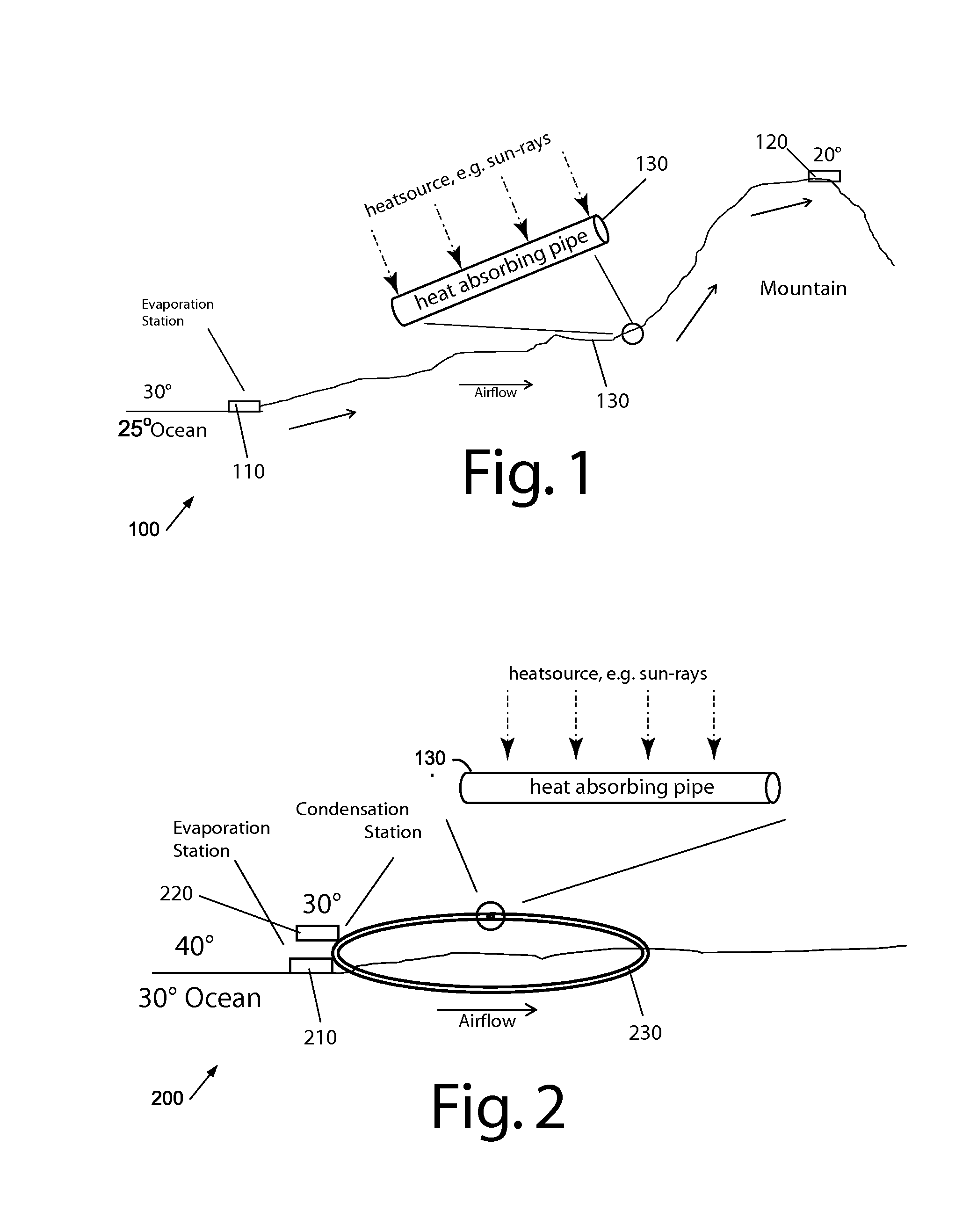
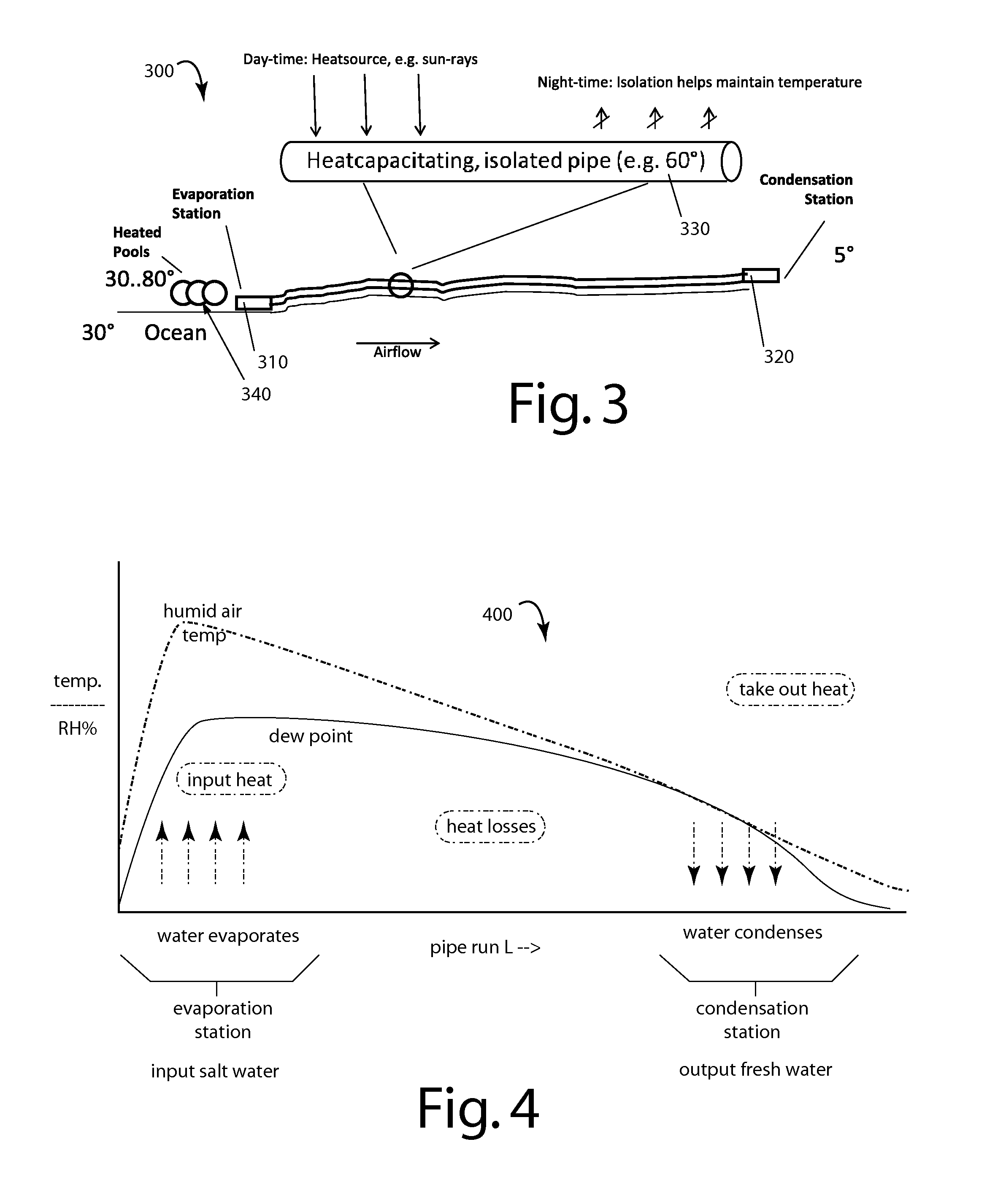
[0023]Large amounts of water vapor can be easily transported long distances and even uphill with very little expenditure of energy. In warm dry climates, natural water evaporation efficiencies can be set to work to put humid air where it can best be used to improve and realize surprisingly practical water desalination.

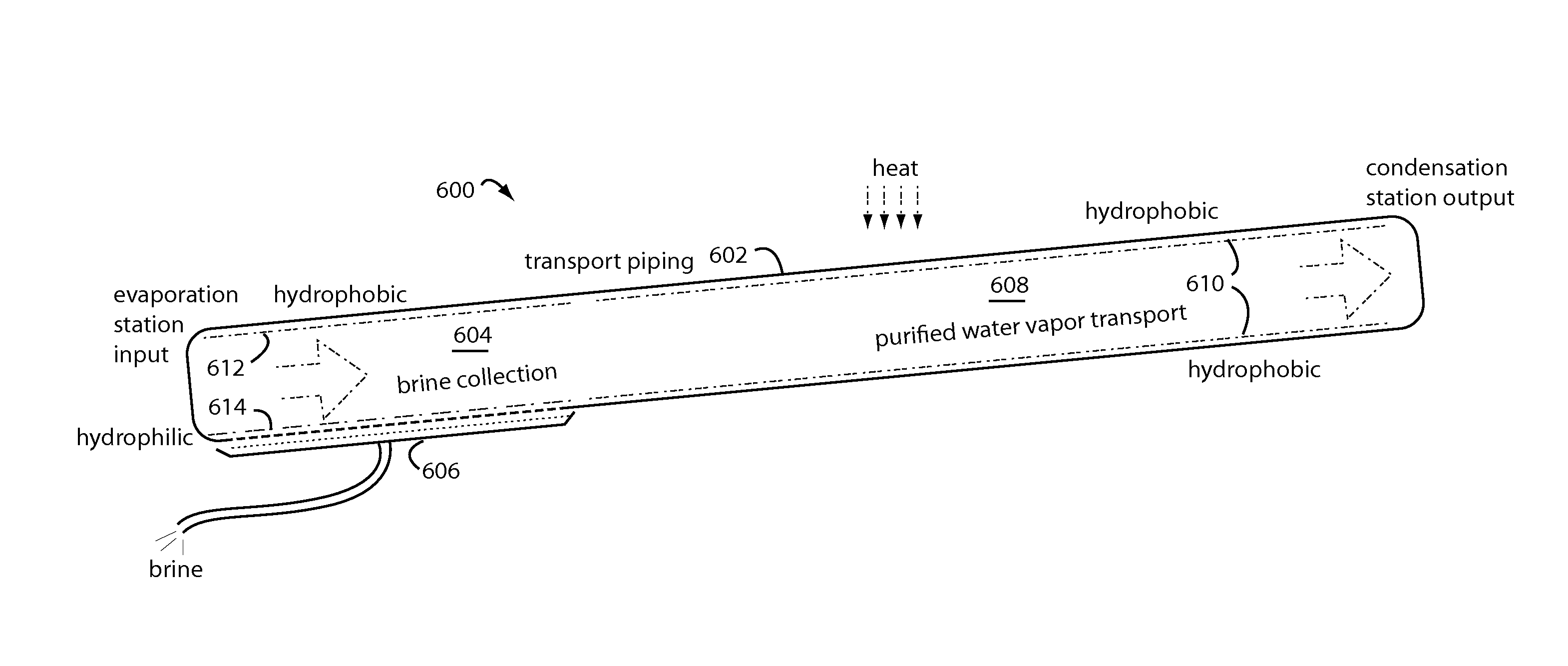
[0024]Water supply system embodiments of the present invention include an evaporation station located at a salt water or other raw water source, long air conduit or pipe to collect natural heat and carry humidified air, and a condensation station with a fresh water outlet. Air pressure changes are induced at various parts of the system to stimulate evaporation and to provoke condensation.

[0025]These systems will work for most minerals, not only salt. Impure water can be freed from a number of non-evaporable substances, e.g., selenium, as in pollution clean-up purposes.

[0026]The typical pipe can be as little as ten meters long, or as long as tens of kilometers with cros...


PUM

PropertyMeasurementUnit
Temperatureaaaaaaaaaa
Pressureaaaaaaaaaa
Relative humidityaaaaaaaaaa

Abstract

Water supply systems use readily available heat sources like the sun and waste heat from industrial plants to heat intake air and water so more water can be used to saturate the intake air. That extra water is condensed out at another place even miles away where the now distilled water would be more useful.

Description

RELATED APPLICATION[0001]This application claims benefit of and is a Continuation-In-Part of International Patent Application PCT / GB2012 / 050673, with a filing date of 27 Mar. 2012, and a priority date of 15 Apr. 2011 (Published as GB2489989A), in the name of Mads Landrok, and titled “Water Supply Systems”. This was thereafter published internationally on 18 Oct. 2012 under number WO / 2012 / 140405.BACKGROUND OF THE INVENTION[0002]1. Field of the Invention[0003]The present invention generally relates to potable water devices and mechanisms, and more particularly to the desalination of large amounts of water at relatively very little expense of energy.[0004]2. Background of the Invention[0005]Large-scale desalination typically requires large amounts of energy and specialized heavy equipment, making it much more costly than fresh water obtained from rivers, ground water, and other natural sources. The areas of the world that lack adequate sources of natural potable water have no other cho...

Claims


Application Information

Patent Timeline
IPC IPC(8): C02F1/12
CPCC02F1/12B01D1/0035B01D1/0058B01D1/04B01D5/006C02F1/14Y02A20/212
Inventor LANDROK, MADS
Owner LANDROK MADS
Why Eureka
Try Eureka