Equipment for quantum vacuum energy extraction

a quantum vacuum and energy extraction technology, applied in the direction of generators/motors, instruments, optical radiation measurement, etc., can solve the problems of no viable commercialized system for extracting this energy, lack of commercialization, and reduced movement of components or fluid between components, so as to achieve economic and viable commercialization

Inactive Publication Date: 2014-06-12
ROSENDORF CHARLES HILLEL
View PDF2 Cites 5 Cited by
  • Summary
  • Abstract
  • Description
  • Claims
  • Application Information

AI Technical Summary

Benefits of technology

[0019]An object of the present invention is a method of fabricating Casimir cavities that

Problems solved by technology

If the components become too close together in these devices, a problem referred to as “Stiction” occurs, meaning that the movement of the components, or of the fluid between the components, is reduced.
At present, there are no viable c

Method used


Image

  • Equipment for quantum vacuum energy extraction
  • Equipment for quantum vacuum energy extraction
  • Equipment for quantum vacuum energy extraction

Examples


embodiment 100

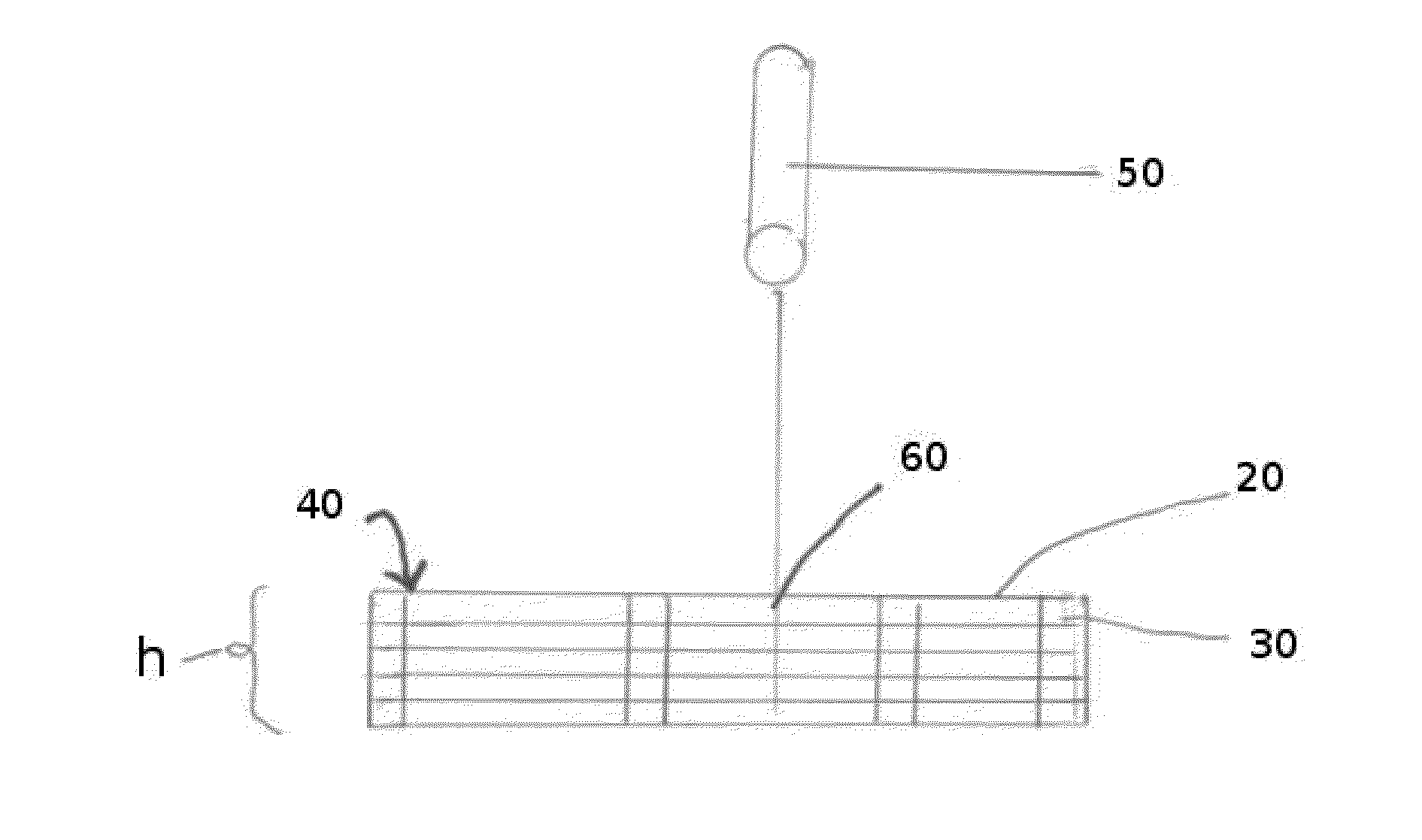
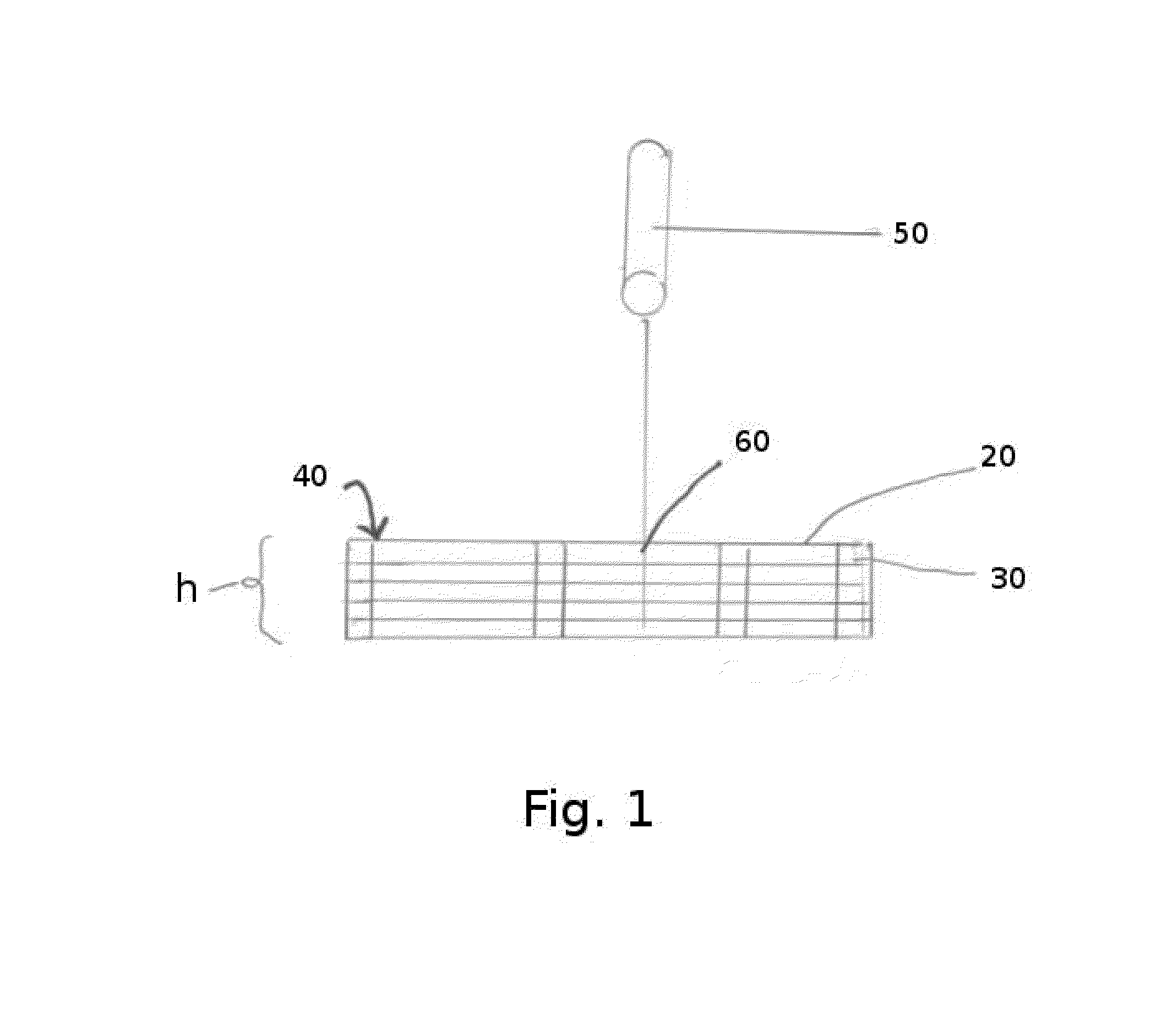
[0125]In this embodiment 100, a plurality of wires 110 may be bundled together and held together by a form fitting filter shell of conducting material 120 such that the fluid is forced through the conducting and non-conducting component.

[0126]The wires 110 may a have cross-section that is circular (round) or otherwise shaped as desired.

[0127]Because gaps will exist between the wires 110, even when packed together, the gaps 130 provide a channel through which gas can flow, and thereby effect a Casimir device (FIG. 3). The wires utilized may be commercially available wires having a narrow diameter, or wires extruded, drawn, rolled, spun, molded, or stamped to have thicknesses / diameters at either the sub-micron, micron, or millimeter size. The wires may be manufactured from any conducting material, such as, but not limited to aluminum, copper, silver, metallically doped or metallically coated non-conducting wire material. Non-conducting wires can be similarly prepared from a variety of...

embodiment 200

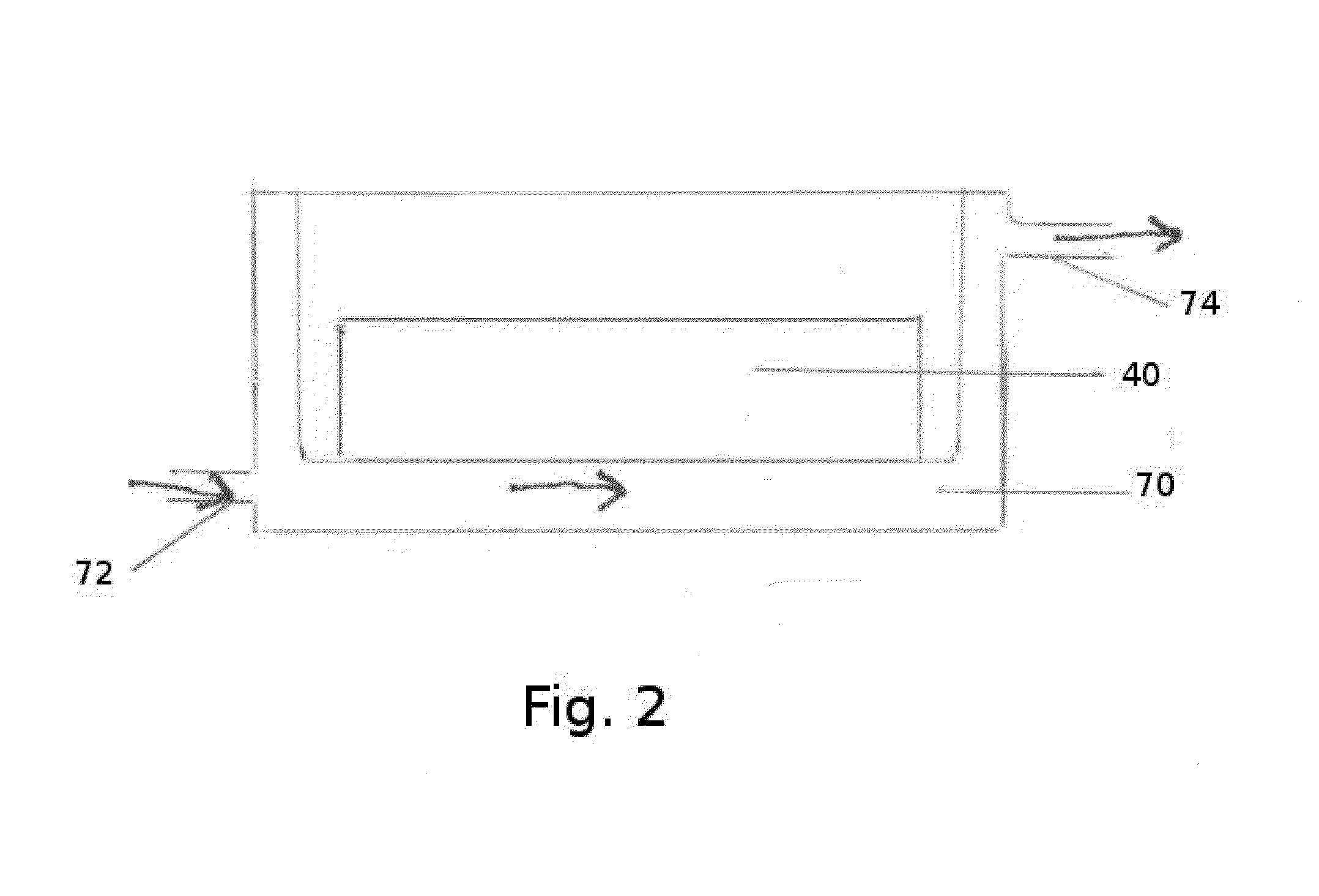
[0130]In this embodiment 200, a plurality of hollow tubes 210 may be bundled together and held together by a form fitting filter shell 220 of conducting material such that the fluid is forced through the conducting and non-conducting component.

[0131]Because gaps 230 will exist between the tubes, even when packed together, the gaps 230 provide a channel through which gas can flow, and thereby effect a Casimir device (see FIG. 6). The tubes 210 utilized may be commercially available tubes having a narrow diameter, or tubes produced by one or more prior-art processes similar to those described above for wires, as appropriate. The tubes 210 may have outer diameters at either the sub-micron, micron, or millimeter size. The tubes 210 may be manufactured from any conducting material, such as, but not limited to aluminum, copper, silver, metallically doped or metallically coated non-conducting material. Non-conducting tubes can be similarly prepared from a variety of non-conducting material...


PUM


Abstract

Embodiments of the present invention comprise different equipment for efficiently and relatively inexpensively producing Casimir cavities for use in quantum vacuum energy extraction. The equipment includes without limitation, sintered materials; submicron porous filter materials; web roll-to-roll produced mesh or foil layers; nanotube arrays; web roll-to-roll produced porous membranes such as graphene, metallically doped; web roll-to-roll produced metallic crystals with self assembling arrays of nano-channels; materials produced by three-dimensional prototyping; materials produced by charged particle deposition; metal wire bundles; metal tube bundles; and metallically doped or metallically coated glass or polymer wire bundles.

Description

CROSS-REFERENCE TO RELATED APPLICATION[0001]This application is a continuation of and claims the benefit of U.S. Non-Provisional patent application Ser. No. 13 / 632,067, filed Sep. 30, 2012, and whose contents are incorporated by reference herein in their entirety.FIELD OF THE INVENTION[0002]Embodiments of the present invention comprise apparatus for energy extraction from liquids and gases. More specifically, embodiments of this invention comprise apparatus for quantum vacuum energy extraction.BACKGROUND OF THE INVENTION[0003]Presently, as energy needs and costs around the world continue to rise, development of energy resources which are widely available, reasonably priced, and non-polluting is a top priority in many places worldwide.[0004]One potential significant energy source is quantum vacuum energy extraction. This potential energy source is currently the subject of much research and discussion.[0005]Quantum vacuum energy extraction is a source of energy resulting from the zero...

Claims


Application Information

Patent Timeline
IPC IPC(8): H01L31/04
CPCB82Y99/00H02S10/00B82Y30/00H02N11/008
Inventor ROSENDORF, CHARLES HILLEL
Owner ROSENDORF CHARLES HILLEL
Why Eureka
Try Eureka