
Omnidirectional Camera

a technology of omnidirectional camera and camera body, which is applied in the field of omnidirectional camera, can solve the problems of obstructing the photographing of a landscape, obstructing the viewing field, and displacement, and achieves the reduction of vertical camera unit, omnidirectional camera miniaturization, and the improvement of the measurement accuracy of position information obtained by inertial measurement uni

Active Publication Date: 2014-06-12
KK TOPCON
View PDF10 Cites 32 Cited by
  • Summary
  • Abstract
  • Description
  • Claims
  • Application Information

AI Technical Summary

Benefits of technology

The present invention provides an omnidirectional camera that can capture images without obstructed views or distortion. Additionally, the camera can improve the accuracy of positional information based on GPS signals. The camera includes a cylindrical mounting frame with horizontal and vertical camera units, as well as a ring-like GPS antenna. The arrangement of the camera and GPS antenna ensures accurate positioning even when the camera and GPS antenna are moving. The camera also includes an inertial measurement unit to improve accuracy when measuring position information. The invention further includes a positional information receiving unit to accurately calculate the position of the GPS antenna. This results in a smaller omnidirectional camera that can be used in various applications.

Problems solved by technology

However, in a case of a conventional system, a GPS antenna and a camera are independently provided, there is a problem corresponding to an arrangement of the GPS antenna.
For example, in a case where the GPS antenna is provided near and above the camera, this arrangement is ideal for receiving a GPS signal, but the GPS antenna itself is reflected in the camera which takes images in a zenith direction, which obstructs a photographing of a landscape behind the GPS antenna.
In a case where the GPS antenna is provided above the camera via a pole at a position apart from the camera, there is no problem in receiving the GPS signal, but the GPS antenna and the pole supporting the GPS antenna are reflected in the camera, which obstructs a viewing field.
Also, in a case where the GPS antenna is provided below the camera at a position apart from the camera, since the GPS antenna is positioned below the system, components and devices, e.g. a camera and others may be an obstacle at a time of receiving a GPS signal.
Therefore, a displacement occurs due to an installation error every time.
Therefore, a positional relationship between the GPS antenna and the camera is apt to vary due to a measurement error of a distance between the GPS antenna and the camera or a measurement error of the GPS antenna position on an image and so on.
Further, in a position measurement by using the GPS, in a case where the receiving of the GPS signal is interrupted because of a state of being in a shade of a building or a mountain or the like, a self-position cannot be determined.
Therefore, in a case where the pitch center or the roll center is provided in a lower portion of the vehicle and the camera and the IMU are disposed at positions apart from each other, when the vehicle accelerates / decelerates or turns, the IMU receives an acceleration different from an acceleration of the camera, and there is a problem that an accurate position of the camera cannot be determined.

Method used


Image

  • Omnidirectional Camera
  • Omnidirectional Camera
  • Omnidirectional Camera

Examples


Embodiment Construction

[0028]Description will be given below on embodiments of the present invention by referring to the attached drawings.

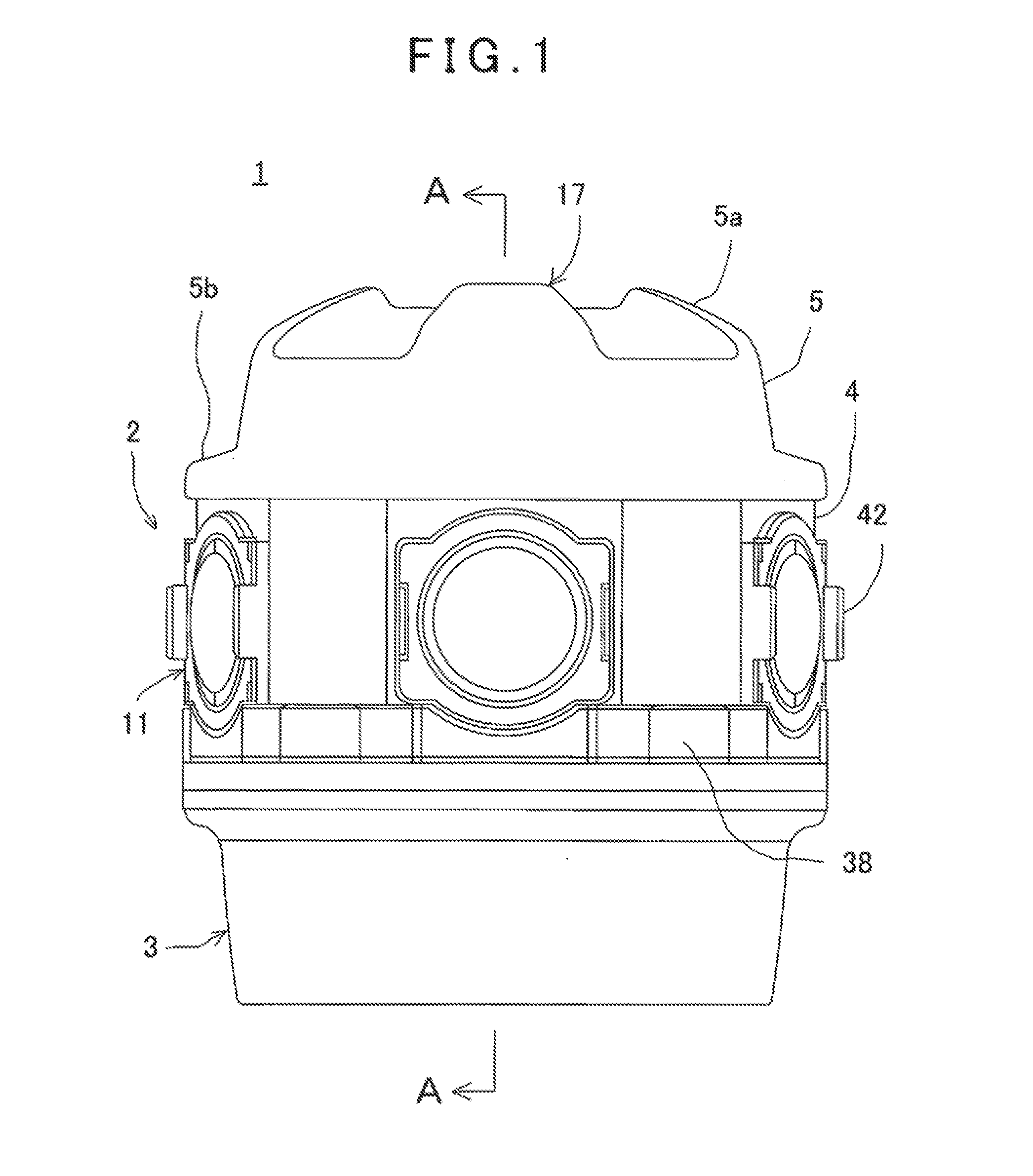
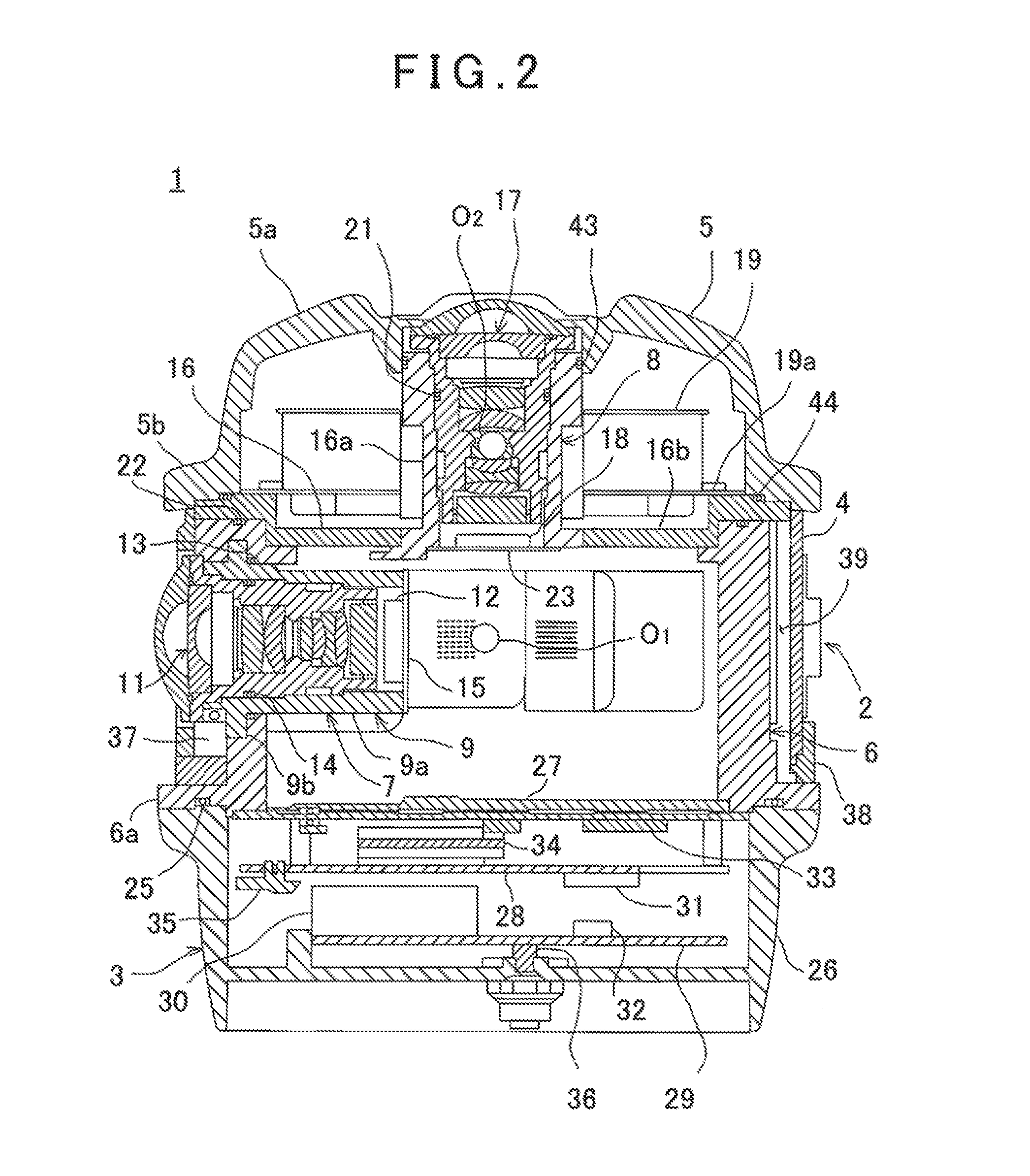
[0029]By referring to FIG. 1 to FIG. 3, description will be given on an omnidirectional camera according to an embodiment of the present invention.

[0030]The omnidirectional camera 1 mainly comprises a camera assembly 2, an image processing unit 3, a body portion cover 4, and an upper cover 5. The image processing unit 3 accommodates an image integrated circuit as an image reception unit, a positional detection integrated circuit as a positional information reception unit, and an electronic circuit or the like. The body portion cover 4 accommodates the camera assembly 2.

[0031]The camera assembly 2 has a camera mounting frame 6 made of a metal material with good heat transfer properties such as aluminum or copper and so on. The camera mounting frame 6 is a cylindrical hollow body, and a circular flange portion 6a is formed concentrically with the camera mounting frame 6 ...


PUM


Abstract

An omnidirectional camera comprises a camera mounting frame 6 of cylindrical hollow body, a plurality of horizontal camera units 7 each of which is provided on a horizontal plane orthogonal to a center line of the camera mounting frame 6 and adapted to acquire an image in a horizontal direction, a vertical camera unit 8 provided so as to coincide with the center line of the camera mounting frame 6 and adapted to acquire an image in a zenith direction, and a ring-like GPS antenna 19 provided so as to surround the vertical camera unit 8.

Description

BACKGROUND OF THE INVENTION[0001]The present invention relates to an omnidirectional camera which takes images of an omnidirectional landscape by a plurality of cameras and which measures a position where images are taken.[0002]In recent years, with spread of a navigation system, not only a positional information as an information of an electronic map but also an image information of a target, a building, a construction, and a landscape around a road or the like are required. Therefore, a measurement for acquiring a positional data as a map information is carried out by using a GPS (Global Positioning System) and, at the same time, an image data is acquired by using an omnidirectional camera.[0003]In recent years, there has been developed a data collection system in which a GPS is mounted in a movable vehicle such as a vehicle, a camera or a laser surveying device (a laser scanner) is mounted, a three-dimensional data of a construction or a building in urban space is collected and i...

Claims


Application Information

Patent Timeline
IPC IPC(8): H04N5/225
CPCG01S19/14H04N5/23238G03B37/04G03B17/02G03B17/24H01Q1/44H04N5/2251G01C21/165G01S19/49G01S19/36H04N23/698
Inventor ISHIDA, TAKESHISASAGAWA, JUNABE, TOMOHIROYAMADA, HIROKAZUAKIMOTO, TETSUYA
Owner KK TOPCON
Learn More