Railway power conditioner for co-phase traction supply system

a technology of power conditioner and co-phase, which is applied in the direction of reducing harmonics/ripples in the ac network, active power filtering, transportation and packaging, etc., can solve the problems of power quality problems, reactive power and harmonics to the power grid, and the traction load is not constant, so as to reduce the high-frequency components of output current and reduce the rating

Inactive Publication Date: 2014-06-12
UNIVERSITY OF MACAU
View PDF3 Cites 44 Cited by
  • Summary
  • Abstract
  • Description
  • Claims
  • Application Information

AI Technical Summary

Benefits of technology

[0008]It is an objective of the present invention to provide a railway power conditioner (RPC) for co-phase power supply system which has a lower rating in comparison with the conventional APCs. By applying the RPC to the co-phase power supply system, it can achieve active power balancing, reactive power compensation and harmonics suppression.
[0009]In accordance with the illustrative embodiment of the present invention, an railway power conditioner includes a DC-AC converter for performing active power injection, reactive power compensation and harmonics suppression; an AC-DC converter for performing power conversion between AC power and DC power; a DC bus coupled between said DC-AC and AC-DC converters for transferring energies; a single-phase isolation transformer connected to the AC-DC converter; a coupling capacitor connected to the DC-AC converter and a filter connected with the coupling capacitor for reducing the high-frequency components of output current of the DC-AC converter.

Problems solved by technology

It is a typical three-phase power supply system with unbalanced loadings, which introduces power quality problems such as voltage unbalance, reactive power and harmonics to the power grid.
In addition, the traction loads are not constant due to the effects of gradients on the track, starting, stopping, shunting and the response of the driver to signals etc.
As a result, the current and voltage unbalance exist at the three-phase high-voltage power grid 110.
This would incur high initial costs to co-phase traction power supply system.

Method used


Image

  • Railway power conditioner for co-phase traction supply system
  • Railway power conditioner for co-phase traction supply system
  • Railway power conditioner for co-phase traction supply system

Examples


Embodiment Construction

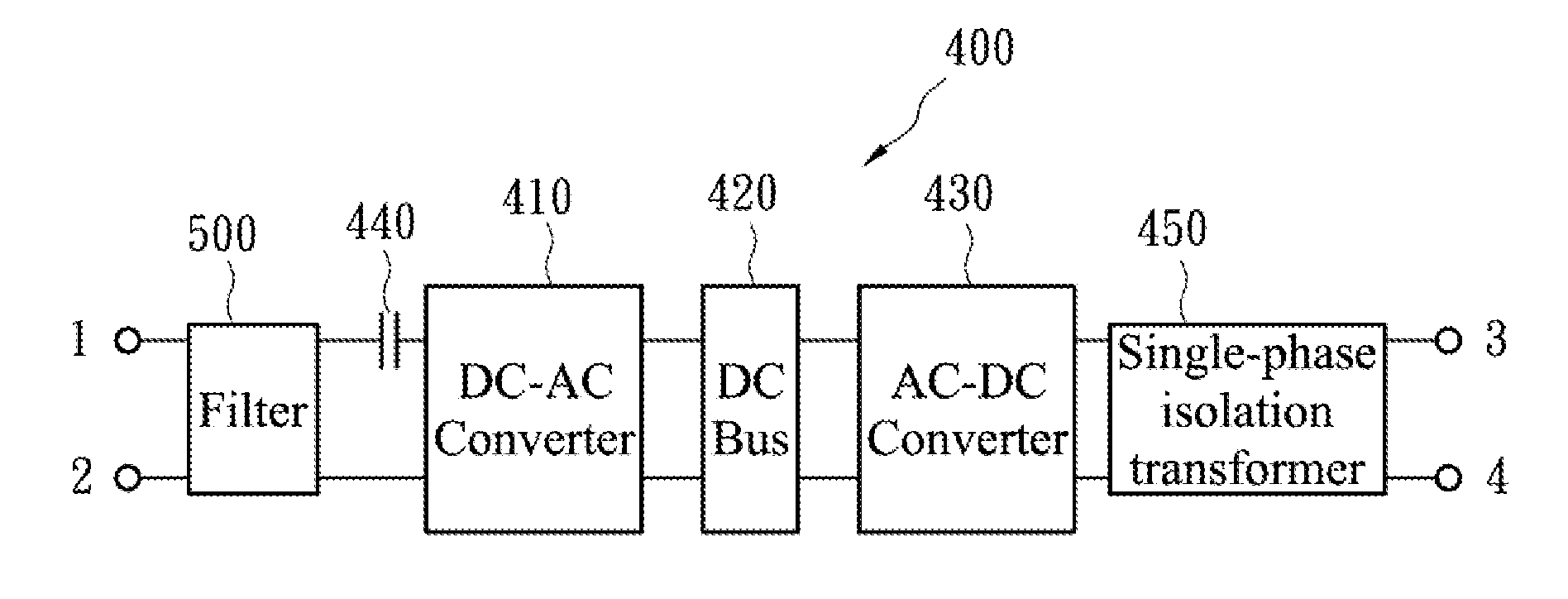
[0021]FIG. 4A is a block diagram of a railway power conditioner (RPC) 400 in accordance with this invention. The RPC 400 includes a DC-AC converter 410, an AC-DC converter 430 and a DC bus 420 connected between these two converters 410 and 430 for power exchanging. Each of the converters 410, 430 is a voltage source converter. The AC-DC converter 430 absorbs power from the high-voltage power grid to reduce the fraction power supply system unbalance and controls a voltage at the DC bus 420. The DC-AC converter 410 injects active power to support traction load; it also injects reactive currents and harmonics to the coupling points at the power supply system.

[0022]The railway power conditioner 400 further includes a filter 500 and a coupling capacitor 440 connected between the filter 500 and the DC-AC converter 410. The capacitance of the capacitor 440 is designed in terms of the required reactive power of the traction loads.

[0023]In order to inject active power to traction load, the D...


PUM


Abstract

A railway power conditioner includes a DC-AC converter and a AC-DC converter for performing power conversion between AC power and DC power, a DC bus connected between the DC-AC converter and the AC-DC converter; a single-phase isolation transformer coupled to an output of the AC-DC converter and a coupling capacitor connected to the DC-AC converter.

Description

FIELD OF THE INVENTION[0001]The present invention generally relates to the field of electric railway power supply systems, and more particularly to a railway power conditioner in railway traction applications.BACKGROUND OF THE INVENTION[0002]Electric railway vehicles such as locomotives or rail coaches powered by an alternating-current (AC) supply line gets the single-phase power from a three-phase power grid via a traction transformer. It is a typical three-phase power supply system with unbalanced loadings, which introduces power quality problems such as voltage unbalance, reactive power and harmonics to the power grid.[0003]FIG. 1 depicts a conventional fraction power supply system 100 for electric railway. A traction transformer 120 is connected to three-phase high-voltage power grid 110. The high-voltage power grid 110 is consisted of three supply lines 111, 112, and 113 and connected to a primary winding of the traction transformer 120. A secondary winding of the traction tran...

Claims


Application Information

Patent Timeline
Patent Type & Authority Applications(United States)
IPC IPC(8): H02M5/42B60M3/00
CPCB60M3/00H02M5/42H02J3/1842B60L9/24H02M5/14H02M5/4585Y02E40/22B60L2200/26Y02E40/40H02J3/01B60L2210/30B60L2210/40Y02E40/20Y02T10/72
Inventor WONG, MAN CHUNGDAI, NING YILAO, KENG WENGWONG, CHI KONG
Owner UNIVERSITY OF MACAU
Why Eureka
Try Eureka