Joint structure and method

Active Publication Date: 2014-06-12
ROLLS ROYCE PLC
View PDF11 Cites 9 Cited by
  • Summary
  • Abstract
  • Description
  • Claims
  • Application Information

AI Technical Summary

Benefits of technology

This patent describes a joint that can withstand larger loads than previous joints. The joint has branches that expand the load over a wider area, allowing it to handle impacts and have a longer lifespan than previous joints. The joint can be attached to a substrate using a cavity in the composite material, which minimizes damage to the reinforcement. The branches are woven into the composite material, improving strength and reducing stress on the branches. The fastening projection is formed on the substrate using additive manufacturing, which allows for complex geometries. Overall, this joint design improves performance and durability.

Problems solved by technology

These are disadvantageous as the apertures / bolts interrupt the structure of the composite and metallic materials, thereby weakening the structure and / or providing a site at which stress concentrations can occur.
Impacts can cause high stress gradients to occur in the vicinity of the apertures.
This can potentially cause damage, particularly to the composite structure.
Also the relatively large thermal mass of the bolts can adversely affect the product upon repeated heating and cooling cycles if the product is intended for use in a hot environment.
This can weaken or otherwise reduce the thermal life of the product.
However any such fasteners are generally disadvantageous as they increase part count, complexity of assembly and may be subject to the stress concentration problems discussed above.
Such protrusions are typically unwanted, and can significantly impact aerodynamic efficiency if the product is intended to be fluid-washed in use.
It is awkward to assemble the composite structure to the metallic structure when adhesive is used.
Furthermore this method introduces another material component at the interface, potentially enhancing the problems associated with the material discontinuity.
Debonding, or other detachment, of the composite is a problem due to stress applied at the interface between materials of differing properties.
Thus debonding can propagate along the joint, thereby reducing its strength, impact resistance, vibration resistance and operational life.

Method used


Image

  • Joint structure and method
  • Joint structure and method
  • Joint structure and method

Examples


Embodiment Construction

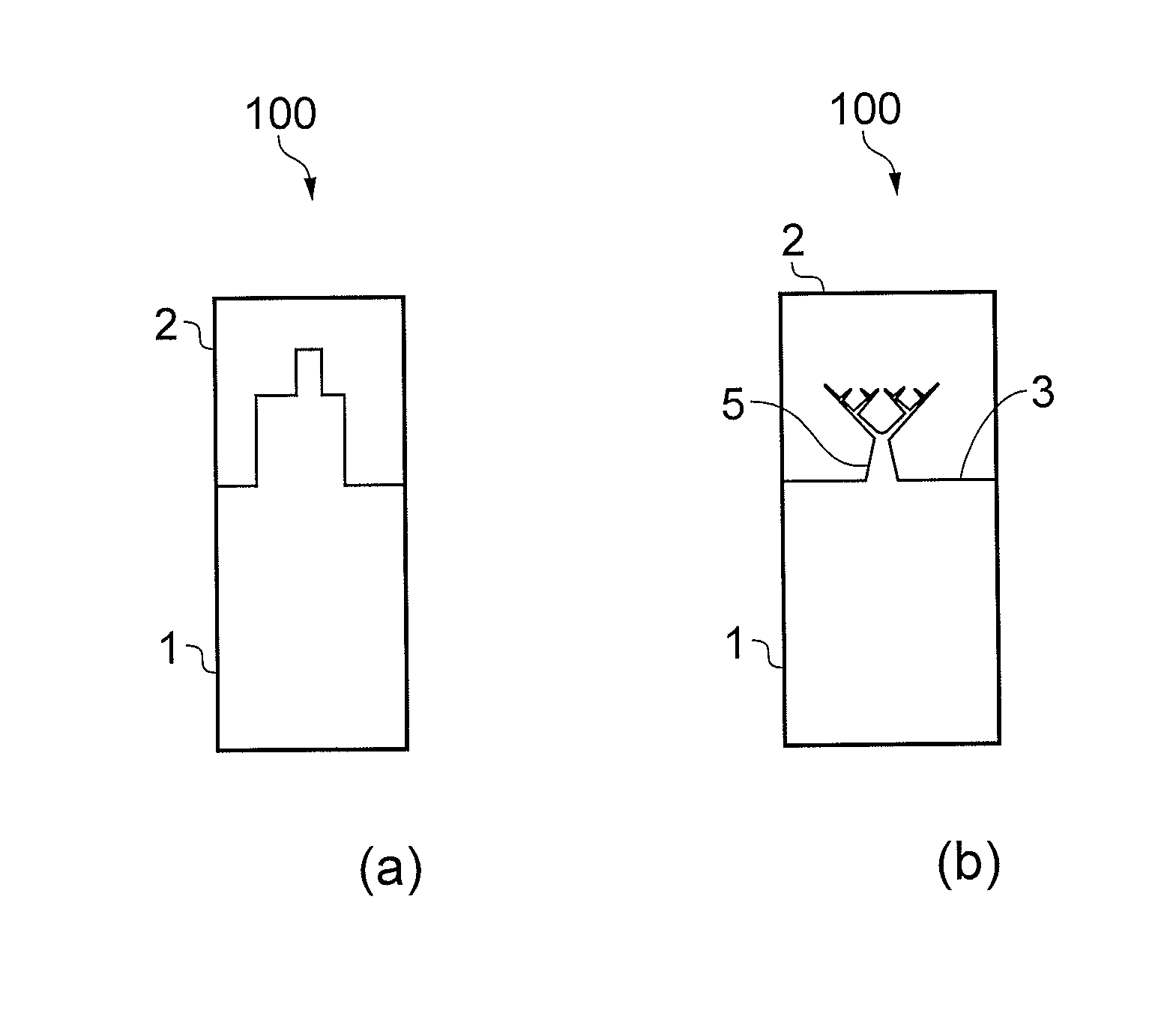
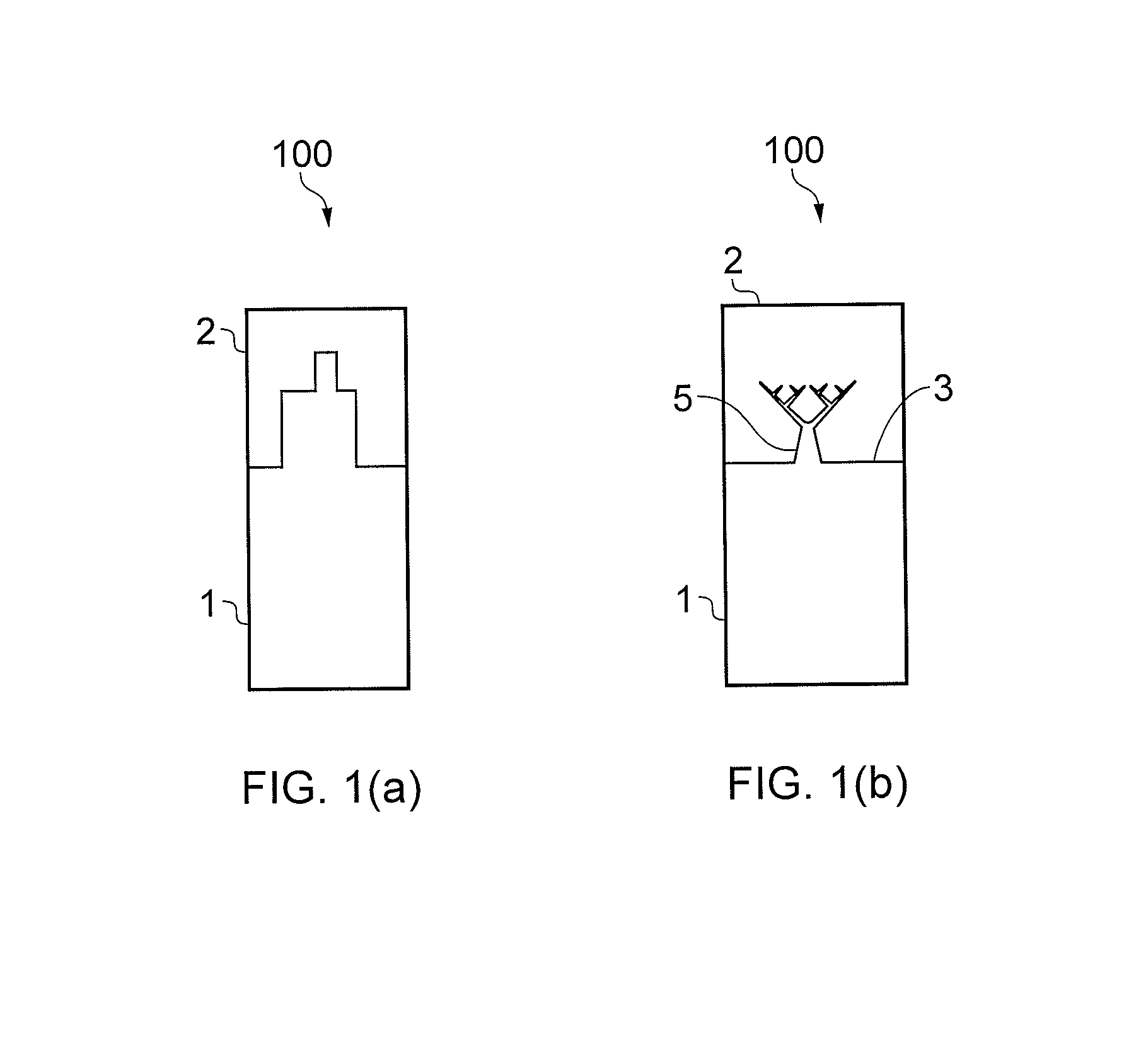
[0055]The invention derives from the realisation that is possible to form structures or fasteners on an outer surface of a substrate which can be embedded in a liquid phase material so as to improve the load-bearing capacity or other operational parameters of the combined structure once the liquid phase material has solidified. One particular implementation of the invention is a joint 100 between a substrate 1 and a composite body 2. A portion of such a joint 100 is shown in FIG. 1(b). The substrate and composite body are herein referred to as respective metal 1 and composite 2 elements of the joint.

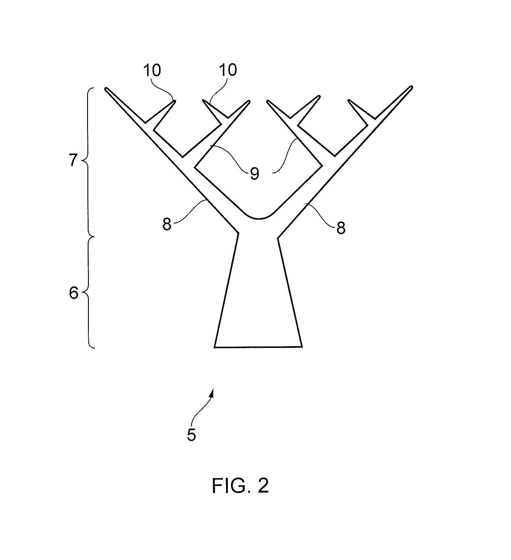
[0056]An upper surface 3 of the metal element 1 is provided with fastening means for fastening the metal element 1 to the composite 2. The fastening means is a plurality of fastening projections 5. The fastening projections 5 are tree-like or tree-root-like, e.g. biomimetic, in form and are upstanding from the upper surface 3 of the metal element 1. The fastening projections 5 are shown ...


PUM

PropertyMeasurementUnit
Volumeaaaaaaaaaa
Shapeaaaaaaaaaa
Deformation enthalpyaaaaaaaaaa

Abstract

The invention relates to a joint including a substrate, optionally a metal substrate, and a body of material joined to the substrate, the body of material typically having a composite portion. An outer surface of the substrate is provided with a fastening projection for fastening the substrate to body of material, wherein the fastening projection has a stem and a plurality of branches having dendritic geometry projecting into the material of the body.

Description

BACKGROUND OF THE INVENTION[0001]This invention concerns joints formed at the interface between adjacent bodies of different materials and, more particularly, although not exclusively to a joint formed with a body of a cured or curable material.[0002]For a number of engineering applications, there is a desire to use composite materials due to the material properties and potential weight savings they can offer. However for many applications it is desirable to form products or components only partly of composite material, whereby the composite material is attached to an adjacent body of different material. The combined material properties may thus be tailored to suit engineering requirements. For example the adjacent material may be provided to improve the strength, temperature resistance or other physical or thermal properties of the final product. In this regard, there is a need to securely join a composite structure to a metallic structure.[0003]Such a need has been identified in a...

Claims


Application Information

Patent Timeline
IPC IPC(8): F16B17/00
CPCB29C65/4835B29C65/54B29C65/565B29C66/1122B29C66/21B29C66/30321B29C66/41B29C66/45B29C66/721B29C66/7212B29C66/73753B29C66/73755B29C66/7394B29C66/742B29C66/7428B29C66/71B29L2031/08B29L2031/3085B29C66/72143B29C66/72141B22F5/009B22F7/002B22F7/062B22F2998/10B22F2999/00B33Y80/00Y10T156/10F16B2200/30B29C65/64Y02P10/25B22F10/25B29K2307/04B29K2063/00B22F2007/042B22F2005/005B22F5/006B29C65/564B29C65/70
Inventor CLARK, DANIELCARE, IAN COLIN DEUCHARALLEN, JEFFREY
Owner ROLLS ROYCE PLC
Why Eureka
Try Eureka