Apparatus for irradiation

Active Publication Date: 2014-06-12
AQUISENSE TECH
View PDF16 Cites 22 Cited by
  • Summary
  • Abstract
  • Description
  • Claims
  • Application Information

AI Technical Summary

Benefits of technology

[0009]In various exemplary embodiments, the present invention provides such an improved apparatus for irradiation that utilizes tailored peak emission wavelengths and combinations of wavelengths, that incorporates an adequate thermal management system, that allows for the recupe

Problems solved by technology

The use of UV LEDs in the fluid treatment market is poised for explosive growth, as water supplies continue to be tapped by growing populations and the pathogen contamination of such wa

Method used


Image

  • Apparatus for irradiation
  • Apparatus for irradiation
  • Apparatus for irradiation

Examples


Example

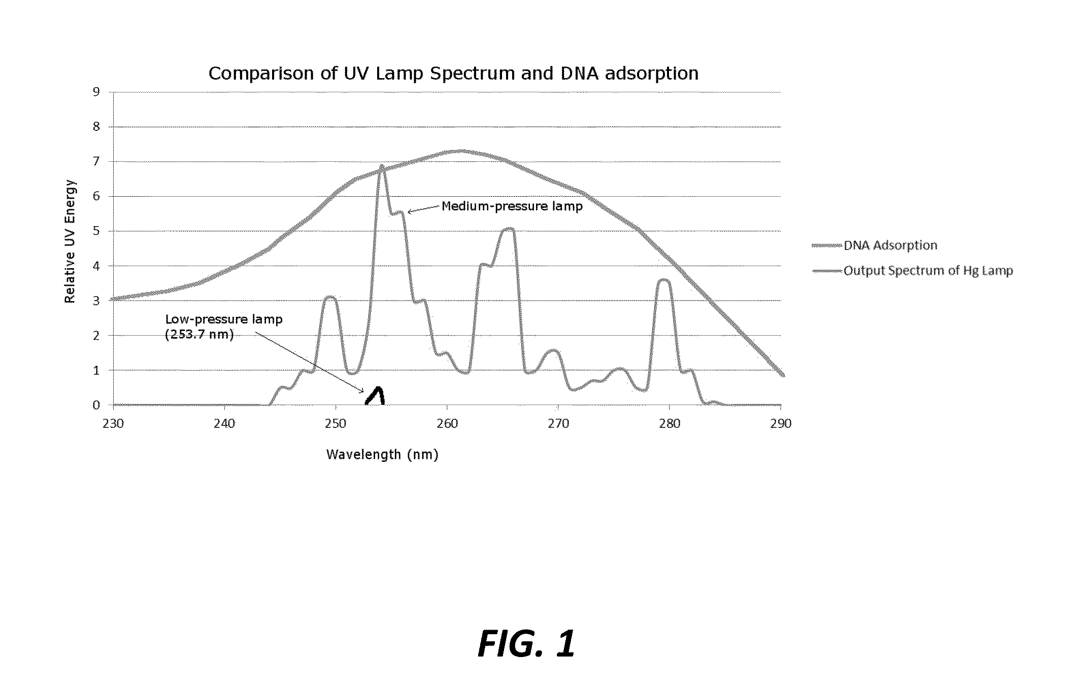
[0023]Referring now specifically to FIG. 1, by way of enabling background, DNA has a peak absorption at about 260 nm, but the absorption curve is broad, with the majority of UV absorption occurring between about 240 nm and about 280 nm. Low and medium pressure Hg lamps have emission peaks at about 253.7 nm, with medium pressure Hg lamps having emission peaks that are narrow and sporadic across the peak microbicidal region of DNA. By comparison, UV LEDs have broadband deep UV emission that can be tailored for peak emission at about 260 nm to provide the maximum dose more effectively than Hg lamps.

[0024]Experimentally determined UV rate constants reported in the literature indicate that some microorganisms are more resistant to UV irradiation than other microorganisms. Several factors affect a microorganism's resistance to UV, including double stranded vs. single stranded DNA, length of DNA, high cytosine and guanine (CG) content of DNA, microorganism size, and shielding effects by ca...


PUM


Abstract

An irradiation apparatus configured to be coupled to an irradiation chamber containing a material to be irradiated, comprising: a support structure; one or more radiation sources coupled to the support structure; and a heat exchange mechanism thermally coupled to the one or more radiation sources. The heat exchange mechanism comprises one or more of a thermoelectric cooling device, a vapor chamber, a heatsink, a heat dissipation structure, a fan, and a cooling coating. The one or more radiation sources comprise one or more UV radiation sources, one or more UV-C radiation sources, one or more visible radiation sources, or a combination thereof. Optionally, the one or more radiation sources comprise a plurality of radiation sources arranged in an array. Optionally, the one or more radiation sources deliver a combination of wavelengths to the material to be irradiated.

Description

CROSS-REFERENCE TO RELATED APPLICATION[0001]The present patent application / patent claims the benefit of priority of co-pending U.S. Provisional Patent Application No. 61 / 735,734, filed on Dec. 11, 2012, and entitled “APPARATUS FOR IRRADIATION,” the contents of which are incorporated in full by reference herein.STATEMENT OF GOVERNMENT SUPPORT[0002]The present invention was made with U.S. Government support pursuant to Award No. IIP-1059286 by the National Science Foundation (American Society for Engineering Education). Accordingly, the U.S. Government has certain rights in the present invention.FIELD OF THE INVENTION[0003]The present invention relates generally to systems and methods for disinfection by irradiation. More specifically, the present invention relates to an apparatus for irradiation.BACKGROUND OF THE INVENTION[0004]It is well known to those of ordinary skill in the art that fluids, including liquids and gases, as well as solids, may be disinfected using radiation, such a...

Claims


Application Information

Patent Timeline
IPC IPC(8): A61L2/08A61L2/16A61L2/10
CPCA61L2/084A61L2/16A61L2/10A61L9/20C02F1/325C02F2305/10
Inventor HARRIS, THEODORE ROBERTPAGAN, JENNIFER GODWINBATONI, PAOLOKRAUSE, JOHN ROBERT
Owner AQUISENSE TECH
Why Eureka
Try Eureka