
Asymmetric magnetic field nanostructure separation method, device and system

a magnetic field and nanostructure technology, applied in the field of nanostructure separation, can solve the problems of limiting the possible number of cnt applications, density gradient separation tends to destroy longer cnts in its processing, and no known process to synthesize chirally pure carbon nanotubes, etc., to achieve high ratio of metallic, conductive or charged nanostructures, and high ratio of semiconducting or insulating nanostructures

Inactive Publication Date: 2014-06-19
THE BOARD OF TRUSTEES OF THE UNIV OF ILLINOIS
View PDF16 Cites 5 Cited by
  • Summary
  • Abstract
  • Description
  • Claims
  • Application Information

AI Technical Summary

Benefits of technology

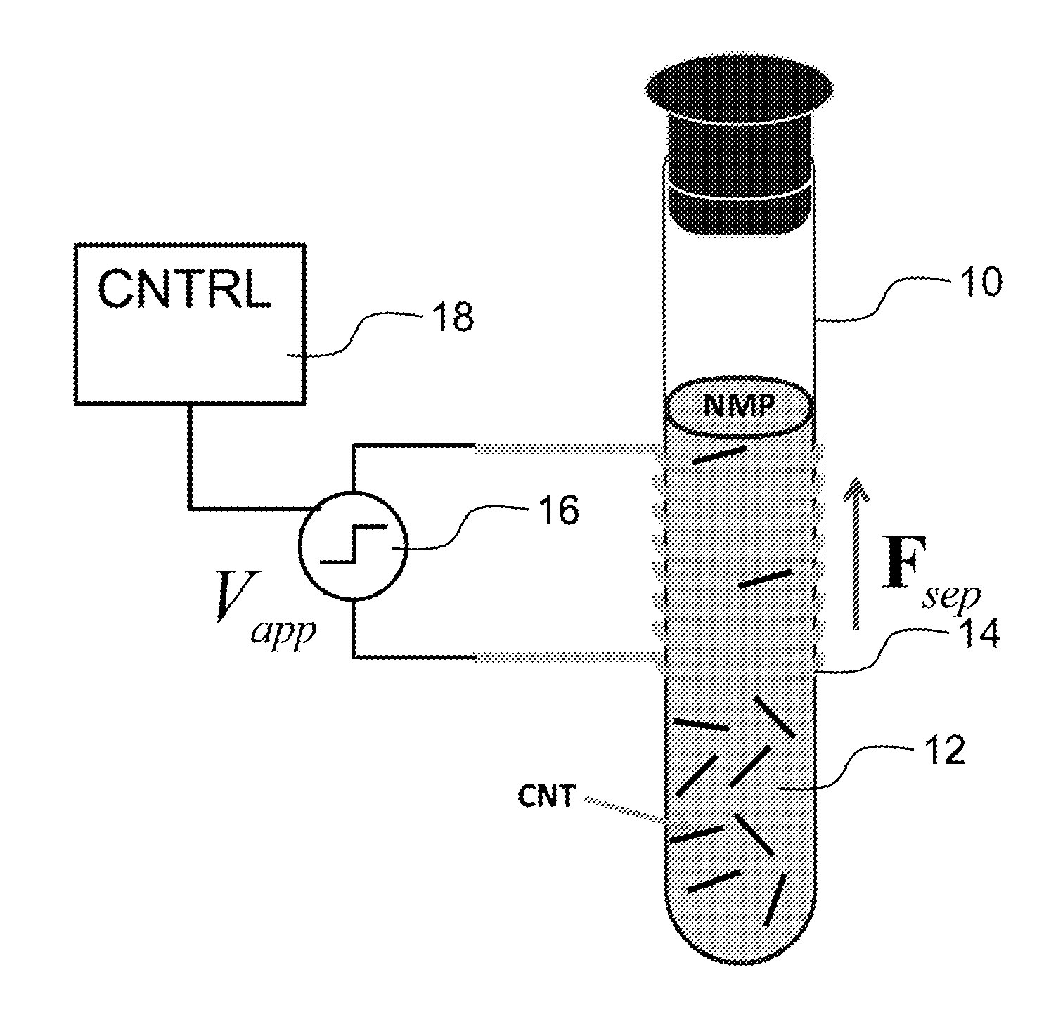
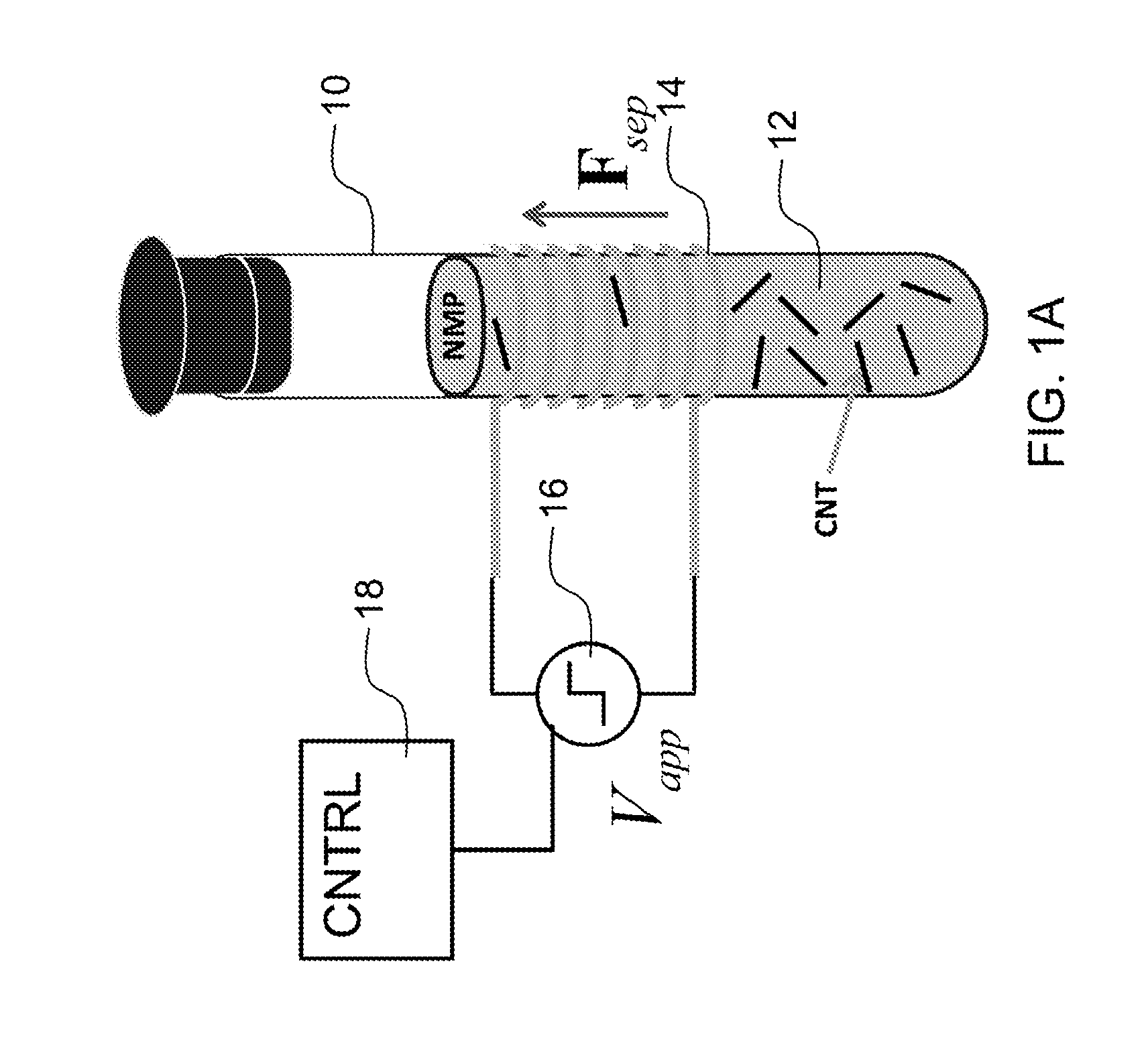
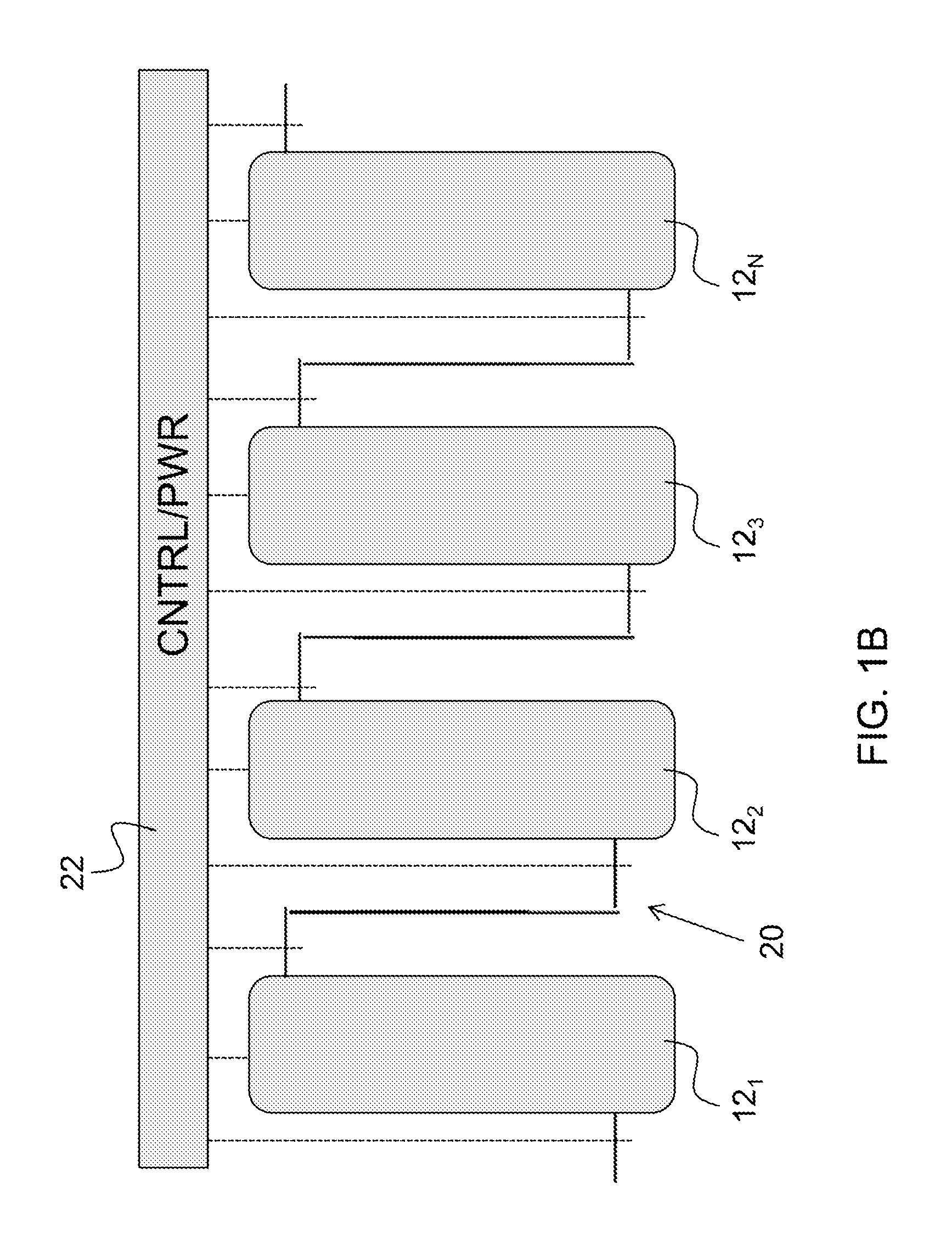
The invention is about a way to separate metallic nanostructures from other nanostructures in solution. This is done using a net Lorentz force that pushes the metallic nanostructures towards a common volume in the solution, while leaving the other nanostructures behind. The common volume is then extracted, resulting in a solution with a high ratio of metallic nanostructures and a low ratio of other nanostructures. This technique can be used to purify metallic nanostructures from other materials.

Problems solved by technology

Normal CNT growth processes give a random distribution of metallic and semiconducting CNTs, limiting the possible number of CNT applications.
As yet there is no known process to synthesize chirally pure carbon nanotubes.
However, density gradient separation tends to destroys longer CNTs in its processing.
Additionally, iterations of the process are expensive.
These machines have a typical cost of $250,000 each.
Adding stages to gradually increase the purity of separated nanotubes adds significant costs.
Another technique, dielectrophoresis, requires pre-deposited metal electrodes on a surface for separation and its scalability is therefore difficult.
This technique is complicated by sensitivity to the solution, contact metals, voltage waveform, contact separation, separation time, and surface employed, making consistent separation challenging.
For scalability and purity of CNTs, the requirement to deposit on electrodes to achieve separation is a limiting factor.
This technique is highly selective, but is slow, expensive and not readily scaled.
Another issue with prior techniques such as density gradient ultrasonification is their inability to work without surfactants.

Method used


Image

  • Asymmetric magnetic field nanostructure separation method, device and system
  • Asymmetric magnetic field nanostructure separation method, device and system
  • Asymmetric magnetic field nanostructure separation method, device and system

Examples


Embodiment Construction

[0017]The present inventors have recognized that it is better to maintain the nanostructures in solution during the process of separation and have provided a method for accomplishing the same that is efficient, scalable and inexpensive. Such solution based separation makes the processes of the invention simpler and amendable to many industrial processes. Process of the invention also work with or without surfactants. Methods of the invention are applicable to nanostructures that can be provided in solution and include a distribution of metallic, semiconducting and insulating nanostructures or a distribution of semiconductor nanostructures of different sizes. Example nanostructures that can be separated by the invention include CNTs, graphene nanoribbons, semiconducting nanowires, and semiconducting quantum dots. Previous CNT electronic separation techniques known to the inventors are limited in their throughput and ability to preserve CNT length. Methods, devices and systems of the ...


PUM

PropertyMeasurementUnit
diametersaaaaaaaaaa
diametersaaaaaaaaaa
Lorentz forceaaaaaaaaaa

Abstract

A preferred method of the invention separates metallic or charged nanostructures in solution. In preferred embodiments, metal and semiconducting nanostructures are separated in solution with use of a net Lorentz force applied to metallic or conductive nanostructures. In other embodiments, charged nanostructures are separated from other nanostructures in solution. The charge can be applied to semiconducting or insulating nanostructures of a predetermined size by application of appropriate radiation. The method is conducted on dispersed nanostructures suspended in solution in a vessel. The net Lorentz force to metallic, conductive or charged nanostructures within the solution moves the metallic, conductive or charged nanostructures toward a common volume in a portion of the vessel. Extraction of the common volume provides solution with a high ratio of the metallic, conductive or charged nanostructures. The solution left behind has a high ratio of semiconducting or insulating nanostructures. That solution can also be recovered.

Description

PRIORITY CLAIM AND REFERENCE TO RELATED APPLICATION[0001]This application claims benefit under 35 U.S.C. §119 and all applicable statues and treaties from prior U.S. provisional application No. 61 / 453,798, which was filed on Mar. 17, 2011 and entitled Asymmetric Magnetic Field Nanostructure Separation Method, Device and System.STATEMENT OF GOVERNMENT INTEREST[0002]This invention was made with government support under contract number N00014-06-10120 awarded by Office of Naval Research. The government has certain rights in the invention.FIELD[0003]A field of the invention is nanostructure separation. A preferred application of the invention particularly concerns the separation of semiconducting carbon nanotubes and metallic carbon nanotubes. Other nanostructures that can be separated include, graphene nanoribbons, semiconducting nanowires, and semiconducting quantum dots.BACKGROUND[0004]Carbon nanotubes (CNTs) are nanometer-sized cylinders of carbon atoms with differing electronic pro...

Claims


Application Information

Patent Timeline
Patent Type & Authority Applications(United States)
IPC IPC(8): B03C1/023
CPCB03C1/023B03C1/0335B03C1/288B03C2201/18B03C2201/26B01J19/12
Inventor LYDING, JOSEPH W.SUBBAIAH, CHARISHMA PULIYANDAWOOD, JOSHUA D.
Owner THE BOARD OF TRUSTEES OF THE UNIV OF ILLINOIS
Learn More