

Organic electroluminescence device and electronic apparatus
a technology of electroluminescence device and electronic apparatus, which is applied in the direction of discharge tube luminescnet screen, discharge tube/lamp details, electric discharge lamps, etc., can solve the problem of not being able to perform a display in a desired color, and achieve excellent display quality and less color deviation
- Summary
- Abstract
- Description
- Claims
- Application Information
AI Technical Summary
Benefits of technology
Problems solved by technology
Method used
Image

Examples
first embodiment
Organic Electroluminescence Device
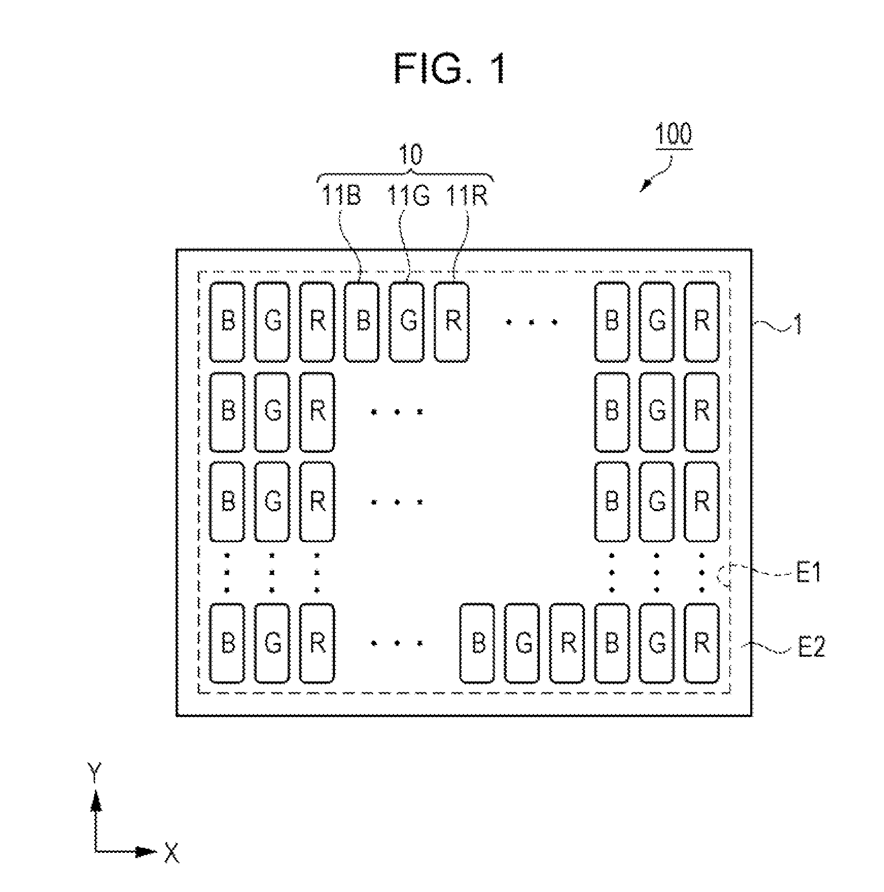
[0037]FIG. 1 is a schematic plan view showing a basic configuration of an organic electroluminescence device according to an embodiment 1.
[0038]First, a schematic ccnfiguration of an organic electroluminescence (EL) device 100 according to the embodiment 1 will be described.
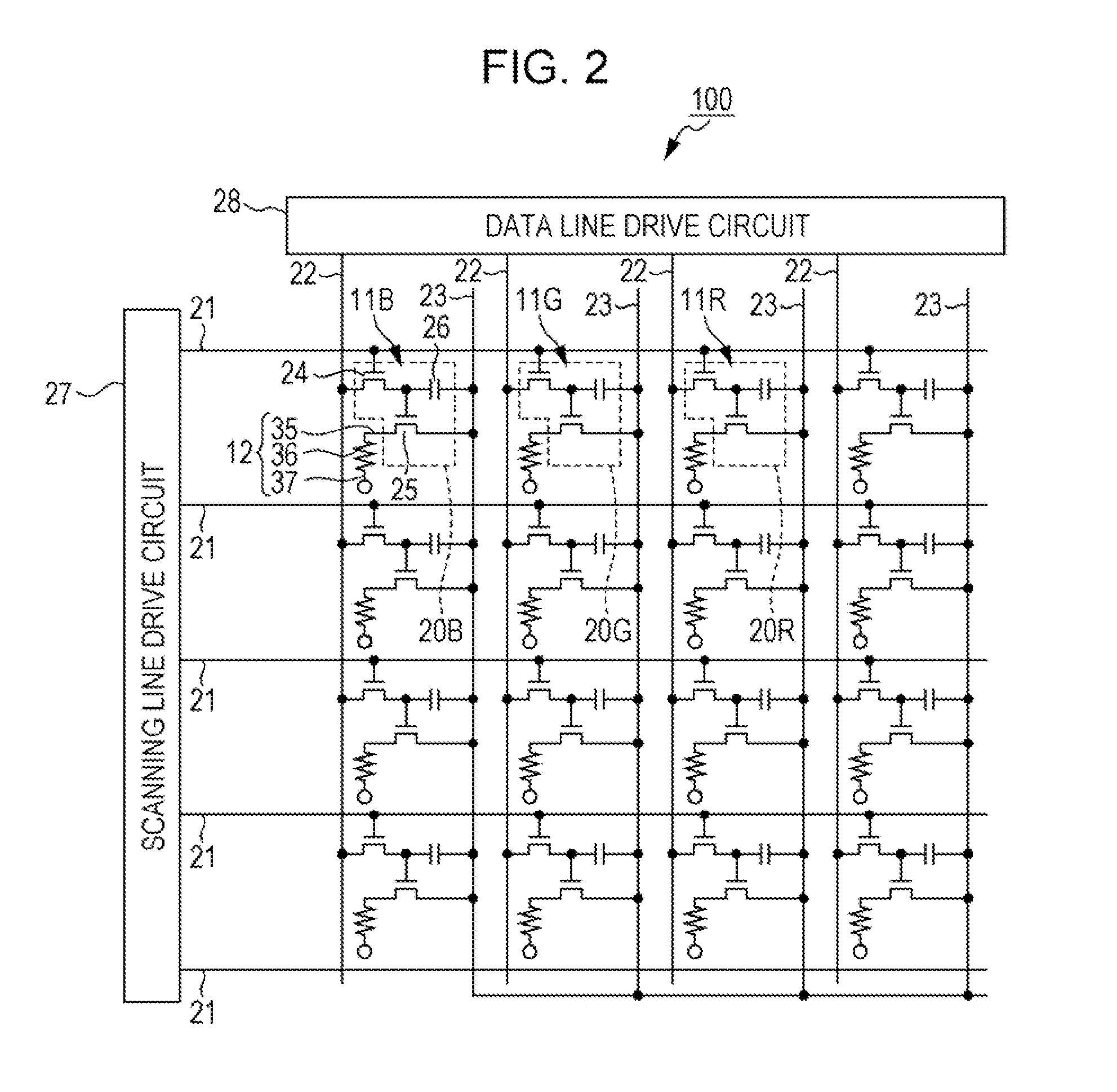
[0039]As shown in FIG. 1, the organic EL device 100 of the embodiment includes a substrate 1, and a plurality of pixels 10 disposed in a display region E1 on a first surface of the substrate 1. In a non-display region E2 between the display region E1 and a peripheral edge of the substrate 1, a peripheral circuit for causing a pixel 10 to emit light is provided. An example of the peripheral circuit includes a scanning line drive circuit, a data line drive circuit, a test circuit, and the like.
[0040]The plurality of pixels 10 is disposed in a matrix shape in the display region E1, and configured to have a plurality of sub-pixels 11 which emit light of different wavelengths, for exa...
first modification example
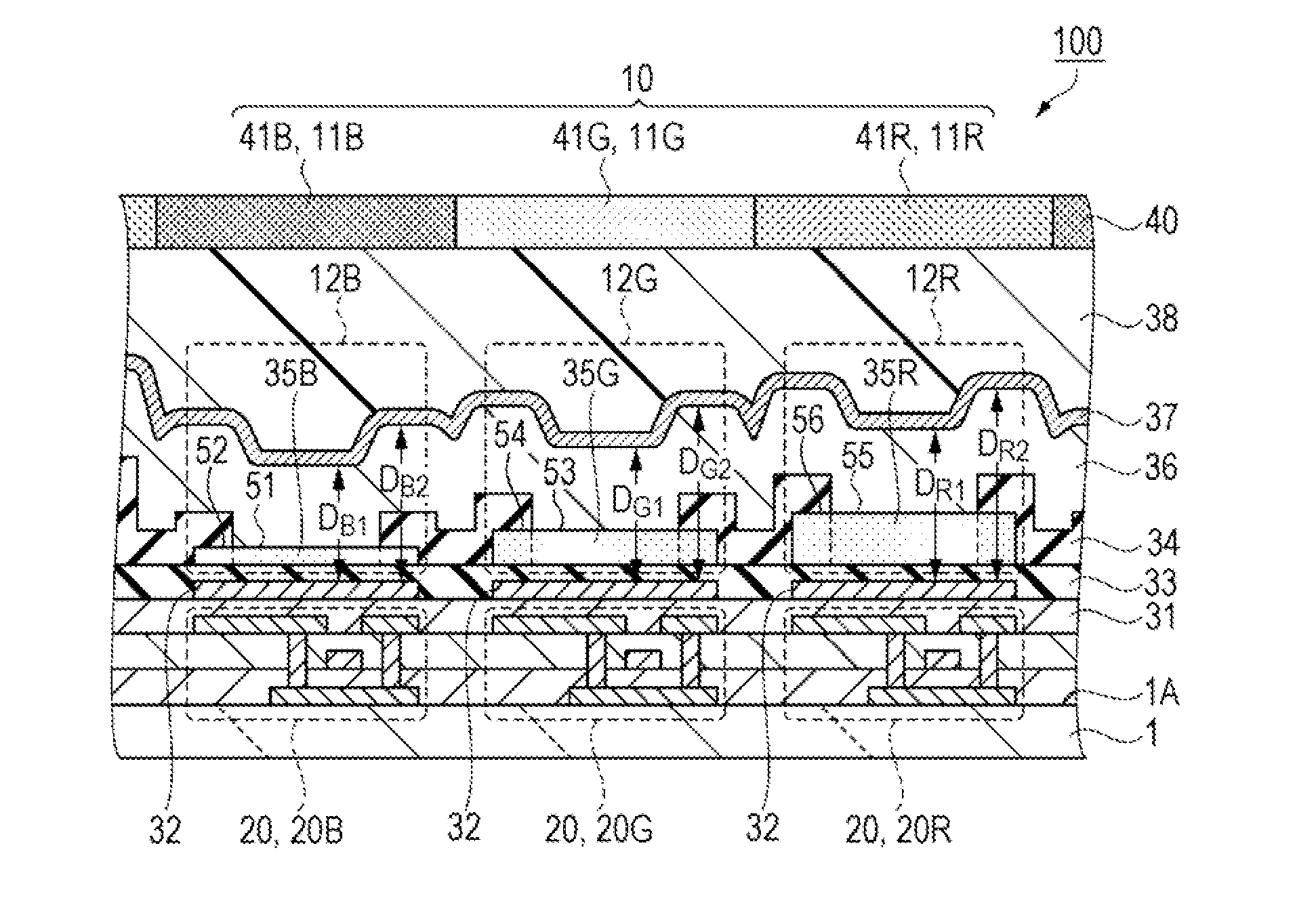
[0124]In the embodiment 1 described above, film thicknesses of the insulation layer 34 disposed in each of the blue sub-pixel 11B, the green sub-pixel 11G, and the red sub-pixel 11R is the same as each other. However, film thicknesses of the insulation layer 34 disposed in each sub-pixel 11B, 11G, and 11R may be different from each other, film thicknesses of the insulation layer 34 disposed in two sub-pixels among these sub-pixels 11B, 11G, and 11R may be the same as each other, and a film thickness of the insulation layer 34 disposed in the remaining one sub-pixel may be different from film thicknesses of the insulation layer 34 disposed in the other two sub-pixels. Specifically, film thicknesses of the insulation layer 34 disposed in the blue sub-pixel 11B and the green sub-pixel 11G may be the same as each other, and film thicknesses of the insulation layer 34 disposed in the blue sub-pixel 11B and the red sub-pixel 11R may be the same as each other. Film thicknesses of the insul...
second modification example
[0126]In addition, in the embodiment 1 described above, the film thickness of the insulation layer 34 is adjusted in all the sub-pixels 11 of blue (B), green (G), and red (R). However, the insulation layer 34 in one type or two types of sub-pixel 11 may have the film thickness which is not adjusted.
[0127]In general, it is known that a green light is easily visible to human eyes, and it is unlikely to sense the color deviation which occurs even if the abnormal luminescence is mixed in light emitted from the luminescence element 12G. In this case, even if the film thickness of the insulation layer 34 disposed in the green sub-pixel 11G is not adjusted, it is possible to provide the organic EL device 100 which has an excellent display quality.
[0128]Similarly, when the color deviation is unlikely to be visible even if the abnormal luminescence is mixed in light emitted from the blue luminescence element 12B, the film thickness of the insulation layer 34 disposed in the blue sub-pixel 11...
PUM
 Abstract
Description
Claims
Application Information