Blade cascade and turbomachine

US20140169977A1Inactive Publication Date: 2014-06-19MTU AERO ENGINES GMBH

Image

  • Blade cascade and turbomachine
  • Blade cascade and turbomachine
  • Blade cascade and turbomachine

Examples


Embodiment Construction

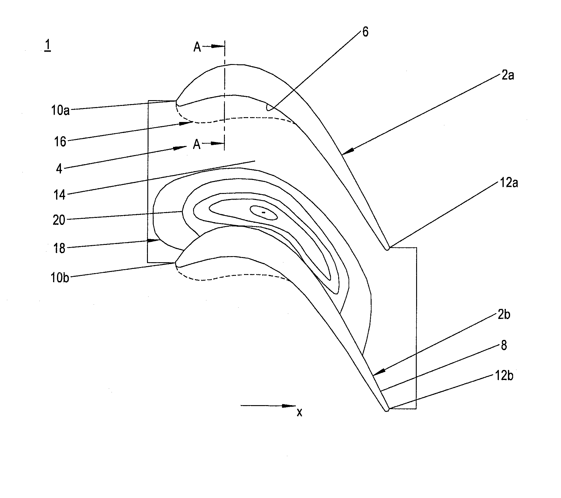
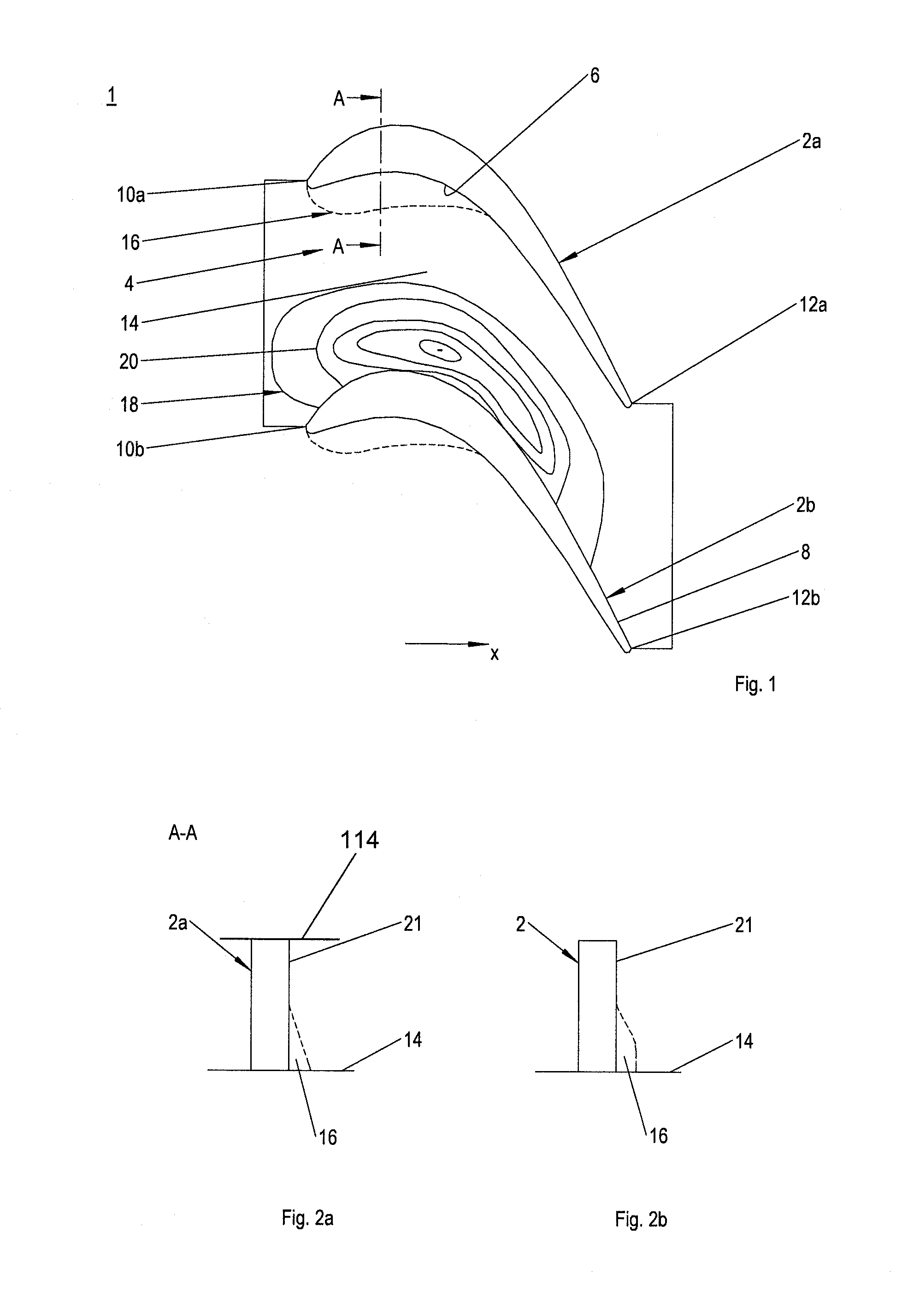
[0025]As shown in the first exemplary embodiment according to FIG. 1, a blade cascade 1 according to the present invention has a plurality of blades 2a, 2b which are situated next to one another in the peripheral direction of blade cascade 1 and which in each case delimit a blade channel 4. Blade cascade 1 is preferably a blade cascade of an axial turbomachine such as an aircraft engine or a stationary gas turbine. For example, blade cascade 1 is situated in the low-pressure turbine of the turbomachine.

[0026]Blade cascade 1 is situated concentrically with respect to a machine axis or rotor axis, not shown, which extends in axial direction x. According to the illustration in FIG. 1, a main flow, not shown, flows through the blade cascade from left to right, the main flow in blade channels 4 being correspondingly deflected in the peripheral direction.

[0027]In the peripheral direction, each blade channel 4 is delimited by a pressure side 6 of first blade 2a and by an oppositely situate...


PUM


Abstract

A blade cascade of a turbomachine having at least one shape variation of a blade situated on the blade side in the proximity of a side wall and extending downstream, and at least one side wall contouring of the side wall or at least one second shape variation of an adjacent blade near the side wall, as well as a turbomachine, are disclosed.

Description

[0001]This claims the benefit of European Patent Application EP 12 197 930.6, filed Dec. 19, 2012 and hereby incorporated by reference herein.[0002]The present invention relates to a blade cascade of a turbomachine, a blade cascade of a turbomachine, and a turbomachine.BACKGROUND[0003]A fluid flow guided through a flow channel is deflected by a lateral pressure gradient parallel to the side wall. Since flow layers close to the wall, due to their low speed, are deflected more than flow layers remote from the wall, a secondary flow is formed which is superimposed on a main flow. This results in pressure losses, among other things. The secondary flows typically arise in blade cascades of turbomachines such as gas turbines and steam turbines. The blade cascades are composed of a plurality of blades, situated next to one another in the peripheral direction, which are situated in a rotationally symmetrical flow channel, and between each of which a blade channel is formed in which the seco...

Claims


Application Information

Patent Timeline
19 Jun 2014
Publication
US20140169977A1
IPC
F01D5/14
CPC
F01D5/143; F01D5/145; F05D2240/123; F05D2240/124; F05D2240/305; F05D2240/306; F05D2250/60; F05D2250/73
Inventors
BRETTSCHNEIDER, MARKUS; MALZACHER, FRANZ