Nucleic acid test apparatus

Inactive Publication Date: 2014-06-19
HITACHI HIGH-TECH CORP
View PDF3 Cites 3 Cited by
  • Summary
  • Abstract
  • Description
  • Claims
  • Application Information

AI Technical Summary

Benefits of technology

[0010]The present invention can provide a nucleic acid test apparatus that is downsized, is capable of measuring a pl

Problems solved by technology

Thus, it is difficult in the conventional technique described in PTL 1 to perform parallel processes for a plurality of specimens having different measurement items.
Further, it is difficult to start processes

Method used


Image

  • Nucleic acid test apparatus
  • Nucleic acid test apparatus
  • Nucleic acid test apparatus

Examples


Example

First Embodiment

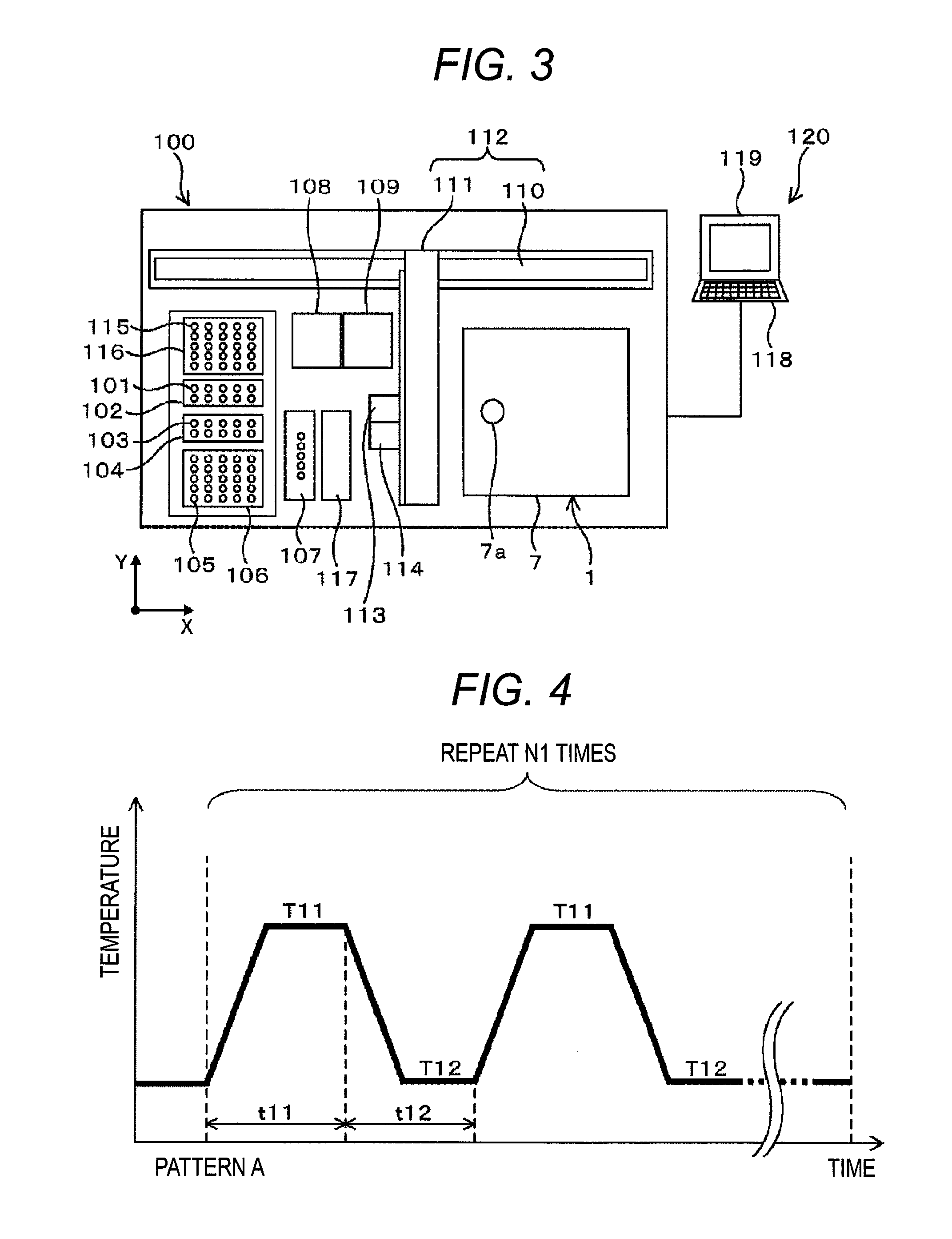
[0023]FIG. 3 is a schematic diagram illustrating the whole configuration of a nucleic acid test apparatus 100 according to the present embodiment. As illustrated in FIG. 3, the nucleic acid test apparatus 100 includes a plurality of sample containers 101 each configured to house a specimen including nucleic acid to be amplified, a sample container rack 102 configured to house the sample containers 101, a plurality of reagent containers 103 configured to house various reagents to be added to specimens, a reagent container rack 104 configured to house the reagent containers 103, a reaction container 105 configured to mix a specimen with a reagent, a reaction container rack 106 configured to house a plurality of unused reaction containers 105, a reaction solution regulation position 107 configured to dispense a specimen and a reagent from the sample container 101 and the reagent container 103 to an unused reaction container 105 with placing the container 105 thereon, a ...

Example

Second Embodiment

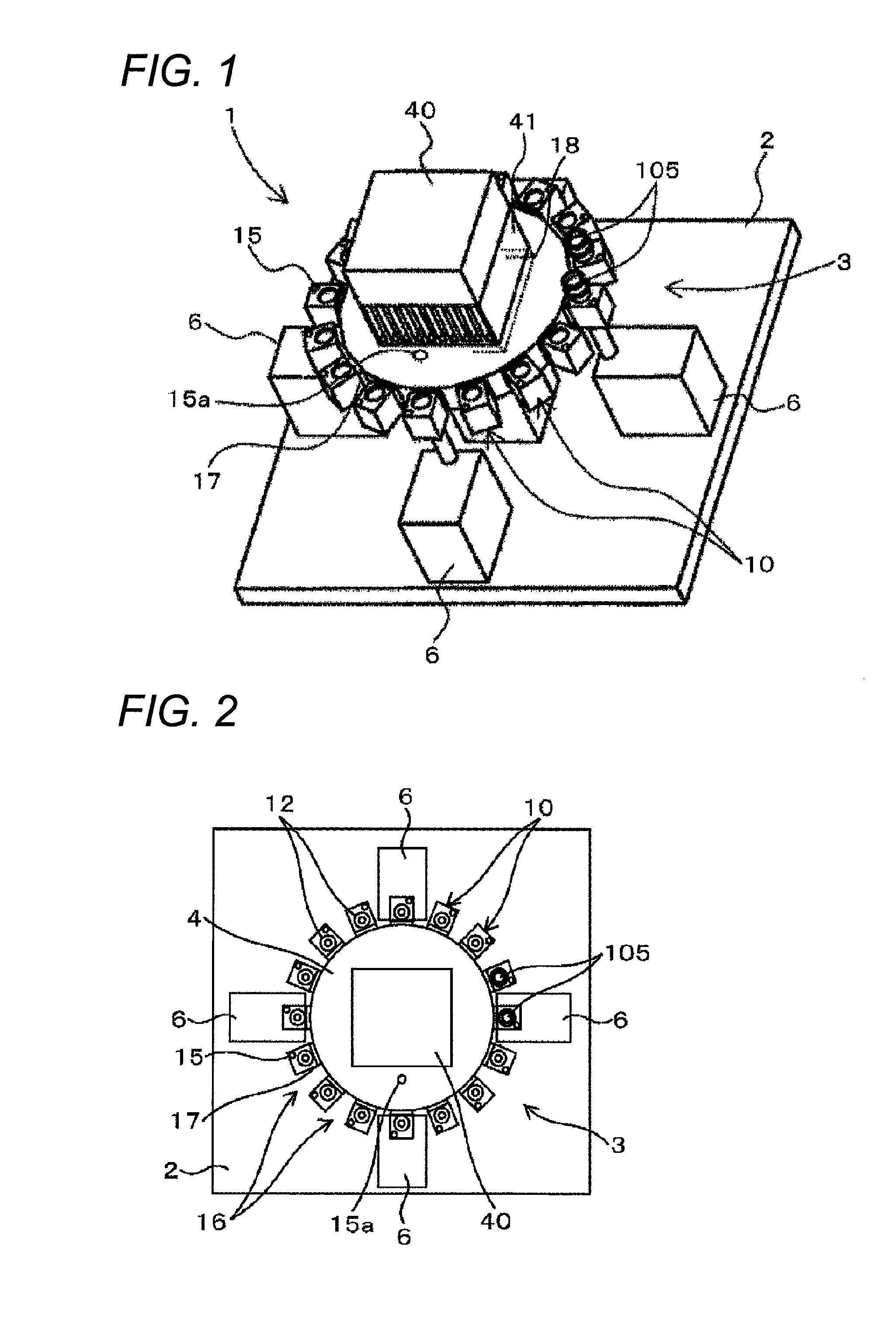
[0048]The method for controlling the positions at which the reaction containers 105 are installed in the nucleic acid amplification device 1 in FIG. 1 will be described in the second embodiment of the present invention with reference to FIGS. 7 and 8.

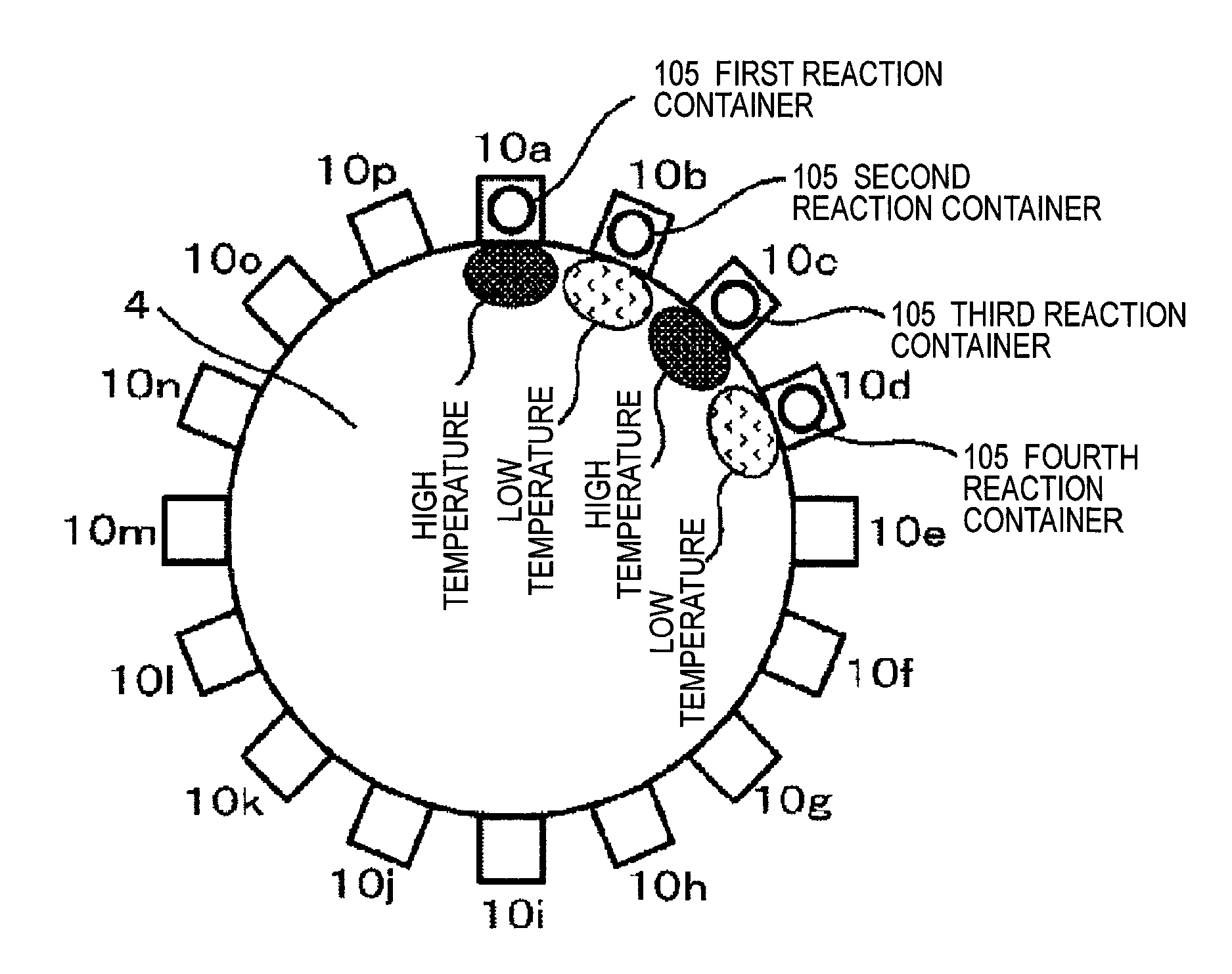
[0049]In the temperature control of the pattern A, for example, when the time t11 is almost the same as the time t12, and each of the time intervals (timings) at which a plurality of reaction containers 105 is continuously installed on a plurality of the temperature regulation blocks 10 is almost the same as a time obtained by adding the time t11 to the time t12, in other words, the reaction container 105 is installed every the time (the time t11+the time t12); the temperature of the temperature regulation block 10 of a first reaction container that is installed first is controlled such that the reaction solution in the first reaction container shows the temperature profile illustrated as S1 in FIG. 7. A second reaction...

Example

Third Embodiment

[0051]The timings for installing the reaction containers 105 and the method for controlling the positions at which the reaction containers 105 are installed in the nucleic acid amplification device 1 illustrated in FIG. 1 will be described in the third embodiment of the present invention with reference to FIGS. 5 and 6.

[0052]In the temperature control in the pattern A, for example, when the time t11 is almost the same as the time t12, and the time intervals at which a plurality of reaction containers 105 is continuously installed on a plurality of the temperature regulation blocks 10 can freely be set, the timing for installing the next reaction container 105 is automatically controlled such that the timing is set at the time after the time t11 has elapsed according to the determination from each piece of the information about the temperature control protocol stored in the control device 120. As a result, the reaction solution in each of the first reaction containers...


PUM


Abstract

The nucleic acid amplification device is configured to amplify the nucleic acid in the reaction solution obtained by mixing a specimen and a reagent and includes a plurality of temperature regulation block configured to hold at least a reaction container provided on a holder base. The order and timings in which the reaction containers are continuously installed on the temperature regulation blocks and in which the temperature regulations of the temperature regulation blocks are started are controlled to minimize the temperature gradient in the holder base.

Description

TECHNICAL FIELD[0001]The present invention relates to a nucleic acid test apparatus for specimens of biological origin.BACKGROUND ART[0002]There is a method, for example, a polymerase chain reaction (hereinafter, referred to as a “PCR”) method as a nucleic acid amplification technique used for a test of the nucleic acid included in a specimen of biological origin. The method specifically amplifies the base sequence to be tested by controlling the temperature of the reaction solution obtained by mixing the specimen and the reagent under a predetermined condition. The method can detect a small amount of nucleic acid at a high sensitivity. Similarly, an isothermal nucleic acid amplification method, for example, a nucleic acid sequence-based amplification (NASBA) method that amplifies the nucleic acid by regulating the reaction solution at a constant temperature is known as another nucleic acid amplification technique. In such nucleic acid amplification methods, many conditions (protoco...

Claims


Application Information

Patent Timeline
IPC IPC(8): B01L7/00
CPCB01L7/52B01J2219/00722B01J2219/00308B01J2219/00495B01L2300/0832B01L2300/0803B01L2300/1822G01N35/025B01L7/5255
Inventor SHOJI, YOSHIYUKIHOSOIRI, TAKEHIKO
Owner HITACHI HIGH-TECH CORP
Why Eureka
Try Eureka