System and method for voltage regulation of a renewable energy plant

a renewable energy and voltage regulation technology, applied in the field of renewable energy sources, can solve the problems of ineffective control system and other voltage regulation devices, increased difficulty in regulating voltage at the point of interconnection in grid distribution applications (e.g. medium voltage or less applications), and reduced voltage at the point of interconnection

Active Publication Date: 2014-06-26
GENERAL ELECTRIC CO
View PDF8 Cites 24 Cited by
  • Summary
  • Abstract
  • Description
  • Claims
  • Application Information

AI Technical Summary

Benefits of technology

[0008]One exemplary aspect of the present disclosure is directed to a method for regulating the voltage at a point of interconnection of a renewable energy plant with a grid. The method includes receiving a voltage signal indicative of a voltage at the point of interconnection and filtering the voltage signal with a high pass filter to generate a filtered error signal. The method further includes generating a reactive power command for the renewable energy plant based at least in part from the filtered error signal and controlling one or more inverters of the renewable energy plant based on the reactive power command.

Problems solved by technology

Conversely, decreasing a reactive power output can typically cause the voltage at the point of interconnection to decrease.
Regulating voltage at the point of interconnection in grid distribution applications (e.g. medium voltage or less applications) can be more difficult.
In addition, the control system can fight other utility voltage regulation devices, such as tap changing transformers, rendering the control system and the other voltage regulation devices ineffective.

Method used


Image

  • System and method for voltage regulation of a renewable energy plant
  • System and method for voltage regulation of a renewable energy plant
  • System and method for voltage regulation of a renewable energy plant

Examples


Embodiment Construction

[0022]Reference now will be made in detail to embodiments of the invention, one or more examples of which are illustrated in the drawings. Each example is provided by way of explanation of the invention, not limitation of the invention. In fact, it will be apparent to those skilled in the art that various modifications and variations can be made in the present invention without departing from the scope or spirit of the invention. For instance, features illustrated or described as part of one embodiment can be used with another embodiment to yield a still further embodiment. Thus, it is intended that the present invention covers such modifications and variations as come within the scope of the appended claims and their equivalents.

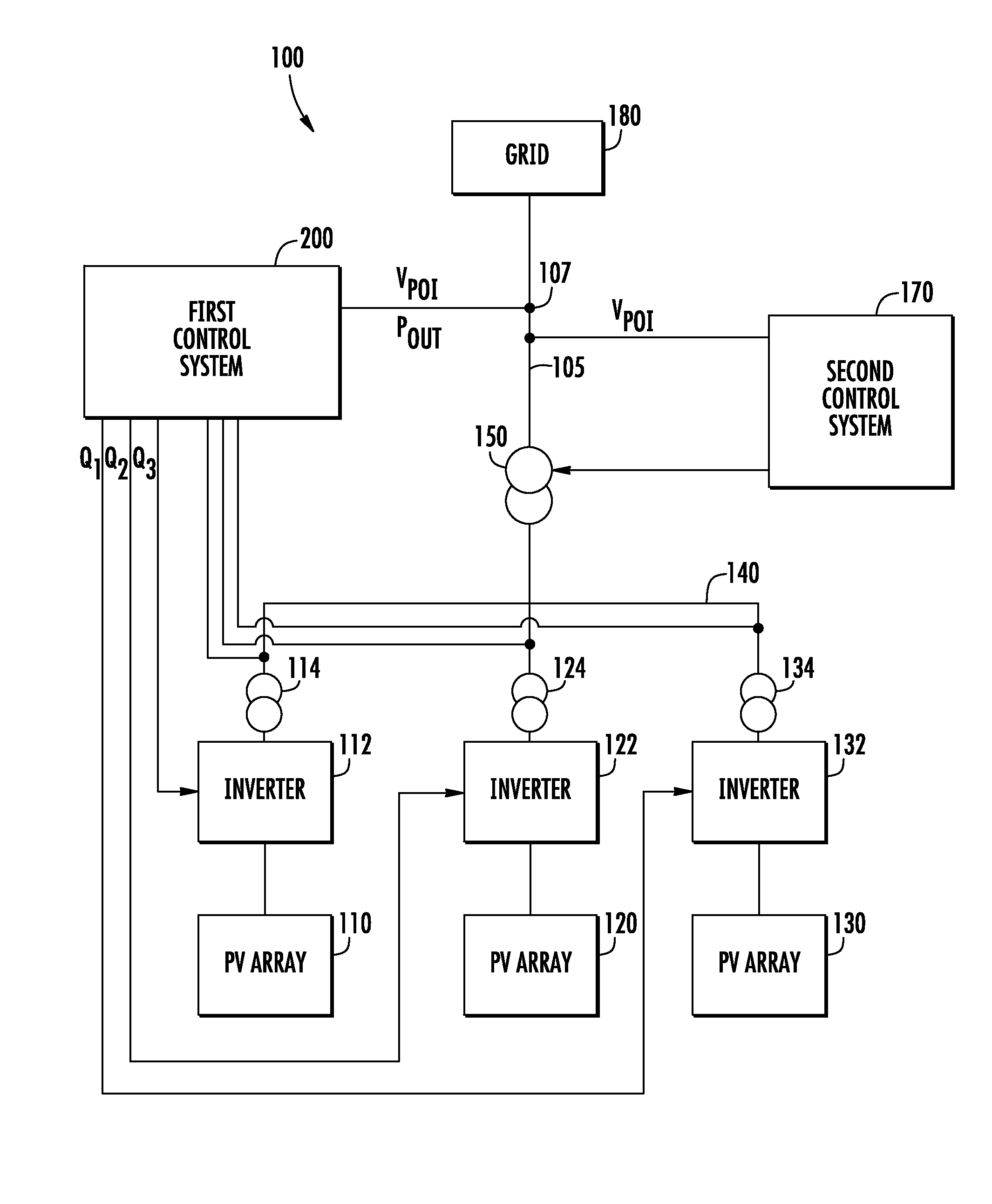
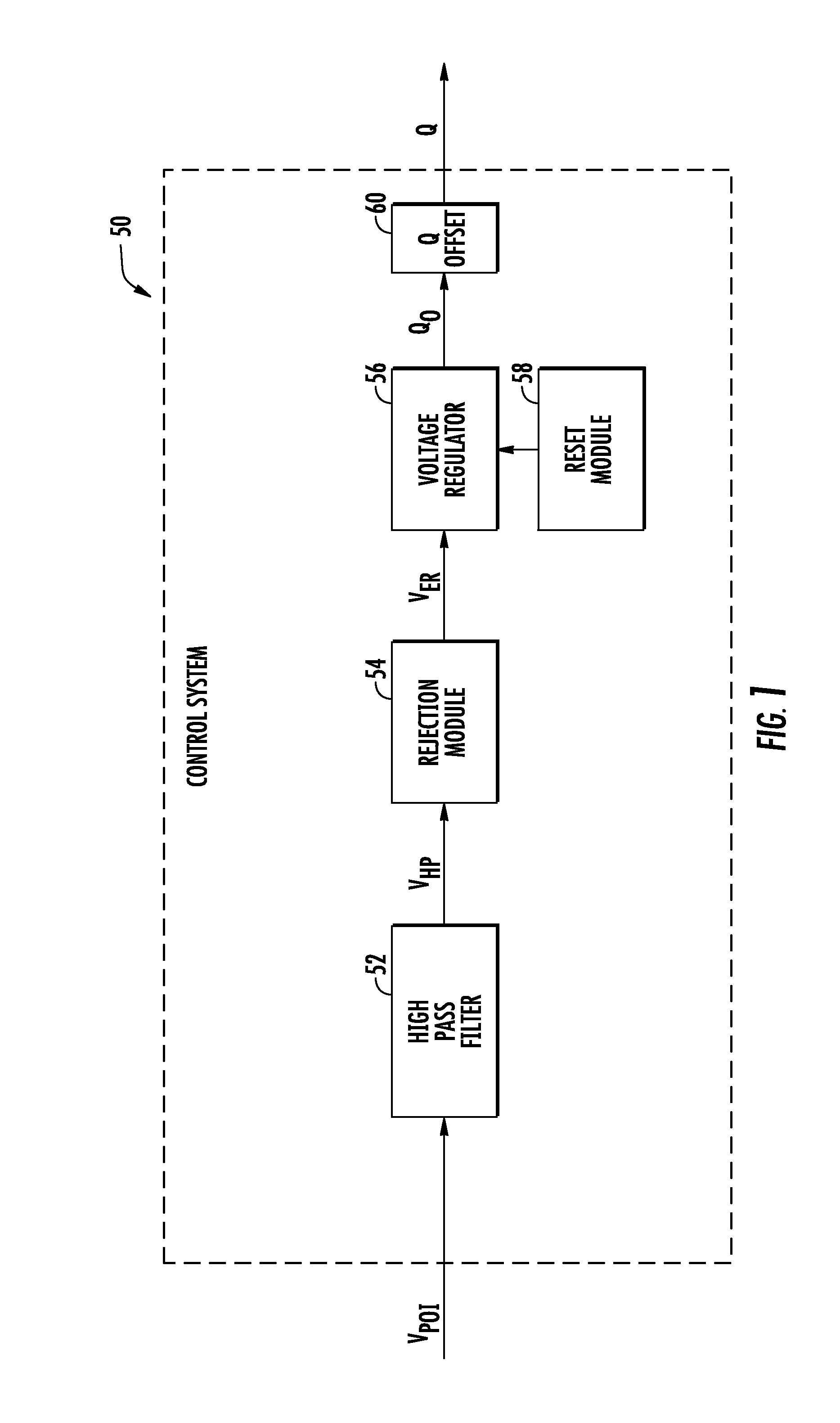
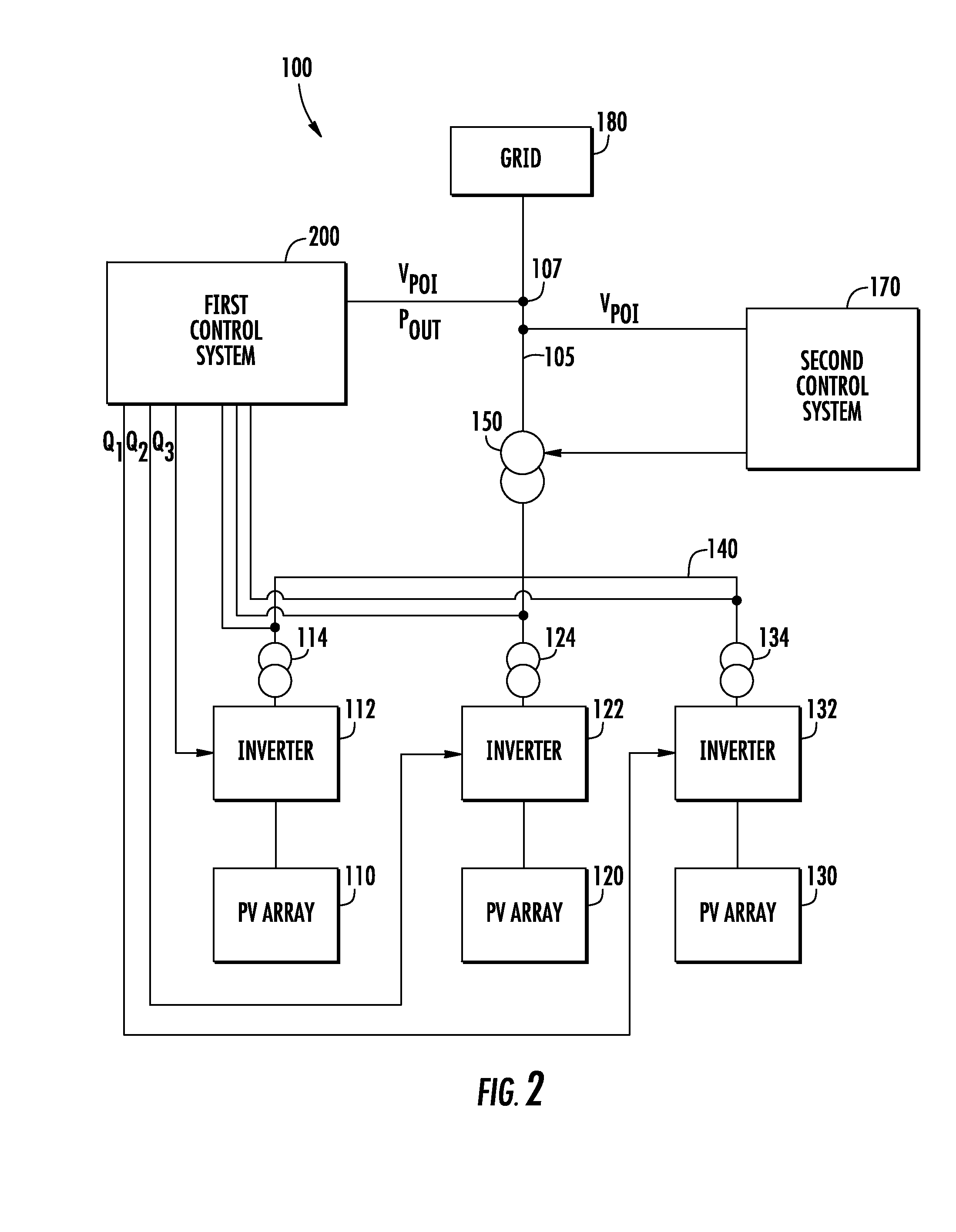
[0023]Generally, the present disclosure is directed to systems and methods for regulating the voltage at a point of interconnection between a renewable energy plant, such as a solar farm, and a grid. The systems and methods can implement a control technique...


PUM


Abstract

Systems and methods for regulating the voltage at a point of interconnection of a renewable energy plant, such as a solar plant, with a grid are provided. A voltage signal indicative of the voltage at the point of interconnection can be received and filtered with a high pass filter to generate a filtered error signal. The high pass filter can block components of the voltage signal at a frequency less than a threshold frequency. A reactive power command for the renewable energy plant can be generated based on the filtered error signal. One or more inverters of the renewable energy plant can be controlled to output reactive power based on the reactive power command. A rejection module can be implemented to prevent adverse interaction with other voltage control devices. In addition, a reset module can be implemented to preserve dynamic reactive power range of the inverters.

Description

FIELD OF THE INVENTION[0001]The present disclosure relates generally to renewable energy sources and more particularly to regulating output of a renewable energy plant.BACKGROUND OF THE INVENTION[0002]Renewable energy sources, such as solar and wind farms, are becoming more economically viable as sources of energy. Renewable energy plants typically include a plurality of power converters configured to convert power generated by the renewable energy source(s) (e.g. photovoltaic arrays, wind turbines, etc.) to AC power suitable for a utility grid. For example, a typical solar farm will include a plurality of inverters configured to convert DC power generated by one or more photovoltaic arrays (PV arrays) to suitable AC power at a grid frequency for application to the utility grid. The plurality of inverters can be coupled to the grid through a transformer at a point of interconnection for the renewable energy plant.[0003]Voltage regulation at the point of interconnection for a renewab...

Claims


Application Information

Patent Timeline
Patent Type & Authority Applications(United States)
IPC IPC(8): H02J4/00
CPCH02J3/16H02J2300/24H02J3/381Y02E10/56Y02E40/30H02J3/50H02J4/00
Inventor SHAO, MIAOLEIBEBIC, JOVANSCHELENZ, OWEN JANNIS SAMUELHART, PATRICK HAMMEL
Owner GENERAL ELECTRIC CO
Why Eureka
Try Eureka