Extended dynamic range optical amplifier

a dynamic range, optical amplifier technology, applied in the direction of optical transmission with multiple stages, electromagnetic transmission, transmission, etc., can solve the problems of large variability or spread loss in the span, useful dynamic range, large loss of db in conventional amplifiers, etc., to achieve high gain, low gain mode, and increase gain

Active Publication Date: 2014-06-26
CIENA
View PDF35 Cites 9 Cited by
  • Summary
  • Abstract
  • Description
  • Claims
  • Application Information

AI Technical Summary

Benefits of technology

[0004]In an exemplary embodiment, an extended dynamic range optical amplifier includes a first gain stage configured to receive an input signal; a first optical switch configured to receive an output of the first gain stage and to switch the output of the first gain stage to one of a first output and a second output; a second gain stage connected to the first output and configured to receive the output of the first gain stage based on a configuration of the first optical switch; a second optical switch including a first input connected to an output of the second gain stage and a second input connected to the second output of the first optical switch, wherein the second optical switch is configured to provide a single output; and a third gain stage configured to receive the single output from the second optical switch. Pursuant to settings of the first optical switch and the second optical switch, the extended dynamic range optical amplifier can be configured to operate in a high gain mode of operation and a low gain mode of operation. The extended dynamic range optical amplifier can further include control circuitry configured to control operation of the first optical switch, the second optical switch, the first gain stage, the second gain stage, and the third gain stage; wherein the control circuitry is configured to set the first optical switch and the second optical switch such that the second gain stage is in line with the first gain stage and the third gain stage in a high gain mode of operation and to set the first optical switch and the second optical switch such that the second gain stage is out of line with the first gain stage and the third gain stage in a low gain mode of operation. The control circuitry can be further configured to selectively increase gain associated with the first gain stage and selectively reduce gain associated with the second gain stage and / or the third gain stage when the extended dynamic range optical amplifier is operating below an associated maximum power.
[0005]The control circuitry can be further configured to, responsive to operation in the low gain mode of operation in a cooperative manner with a Raman amplifier, detect a failure of the Raman amplifier; and, responsive to the failure of the Raman amplifier, switch to the high gain mode of operation. The control circuitry can be further configured to select appropriate operating parameters of the first optical switch, the second optical switch, the first gain stage, the second gain stage, and the third gain stage cooperatively with and / or without a Raman amplifier. The extended dynamic range optical amplifier can further include a pump in the first gain stage; and a residual pump bypass from the pump in the first gain stage to the second gain stage, wherein the second gain stage utilizes residual power from the pump in the first gain stage in lieu of having a pump contained therein. The extended dynamic range optical amplifier can further include a variable optical attenuator disposed between the output of the first gain stage and the first optical switch configured to perform selective attenuation. The extended dynamic range optical amplifier can further include a gain flattening filter at an input of the second gain stage configured to incrementally perform gain flattening. The extended dynamic range optical amplifier can further include erbium doped fiber in each of the first gain stage, the second gain stage, and the third gain stage. The extended dynamic range optical amplifier can include a dynamic range of about 5 dB to 25 dB.
[0006]In another exemplary embodiment, a method of operating an extended dynamic range optical amplifier includes selecting a mode of operation for the extended dynamic range optical amplifier including one of a low gain mode and a high gain mode; responsive to selecting the low gain mode, selectively omitting a second gain stage in the extended dynamic range optical amplifier and amplifying an input signal with a first gain stage and a third gain stage; and, responsive to selecting the high gain mode, selectively including the second gain stage between the first gain stage and the second gain stage and amplifying the input signal with each of the first gain stage, the second gain stage, and the third gain stage. The method can further include selectively omitting or selectively including the second gain stage via a first optical switch and a second optical switch. The method can further include selectively increasing gain associated with the first gain stage and selectively reducing gain associated with the second gain stage and / or the third gain stage when the extended dynamic range optical amplifier is operating below an associated maximum power. The method can further include, responsive to operation in the low gain mode in a cooperative manner with a Raman amplifier, detecting a failure of the Raman amplifier; and, responsive to the failure of the Raman amplifier, switching to the high gain mode. The method can further include operating a pump in the first gain stage; in the high gain mode, using residual pump power from the pump for the second gain stage thereby operating the second gain stage without a pump contained therein.
[0007]In yet another exemplary embodiment, a line amplifier configuration includes an extended dynamic range optical amplifier supporting a first fiber and a second fiber, wherein, for each of the first fiber and the second fiber, the extended dynamic range optical amplifier includes a first gain stage configured to receive an input signal; a first optical switch configured to receive an output of the first gain stage and to switch the output of the first gain stage to one of a first output and a second output; a second gain stage connected to the first output and configured to receive the output of the first gain stage based on a configuration of the first optical switch; a second optical switch including a first input connected to an output of the second gain stage and a second input connected to the second output of the first optical switch, wherein the second optical switch is configured to provide a single output; and a third gain stage configured to receive the single output from the second optical switch; wherein the extended dynamic range optical amplifier is configured to selectively operate in one of a low gain mode and a high gain mode for each of the first fiber and the second fiber. The extended dynamic range optical amplifier can be configured based on a first operating regime, a second operating regime, and a third operative regime based on a combination of span loss of each of the first fiber and the second fiber and fiber type of each of the first fiber and the second fiber; in the first operating regime, the extended dynamic range optical amplifier is operated in the low gain mode without a Raman amplifier; in the second operating regime, the extended dynamic range optical amplifier is operated in one of the low gain mode with a Raman amplifier and the high gain mode without a Raman amplifier; and, in the third operating regime, the extended dynamic range optical amplifier is operated in the high gain mode with a Raman amplifier. In the low gain mode with a Raman amplifier, the extended dynamic range optical amplifier can be configured to detect a failure of the Raman amplifier and switch to the high gain mode based thereon. In the high gain mode, the extended dynamic range optical amplifier can be configured to utilize residual pump power from the first gain stage for the second gain stage in lieu of having a pump contained therein.

Problems solved by technology

However, the useful dynamic range, where the noise figure (NF) of the amplifier does not increase significantly with the reduction in gain, is limited to about 5 dB in conventional amplifiers.
In real networks, there is a large variability or spread in the span losses.
Disadvantageously, multiple types of EDFA modules leads to increased sparing requirements, complex manufacturing, and the like.
The other factors that complicate the design are that the EDFA modules may be coupled in two directions in order to reduce the footprint.

Method used


Image

  • Extended dynamic range optical amplifier
  • Extended dynamic range optical amplifier
  • Extended dynamic range optical amplifier

Examples


Embodiment Construction

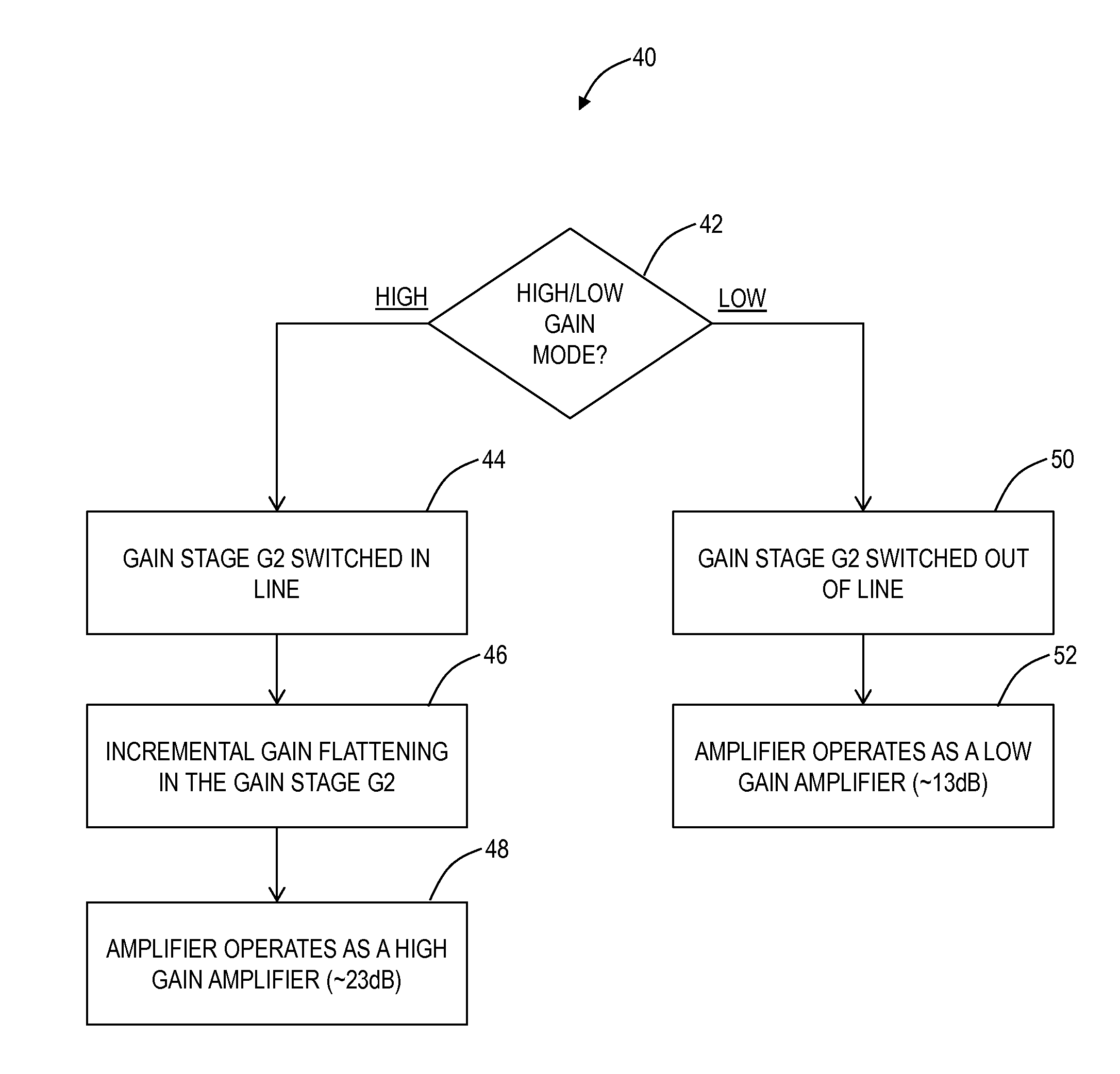
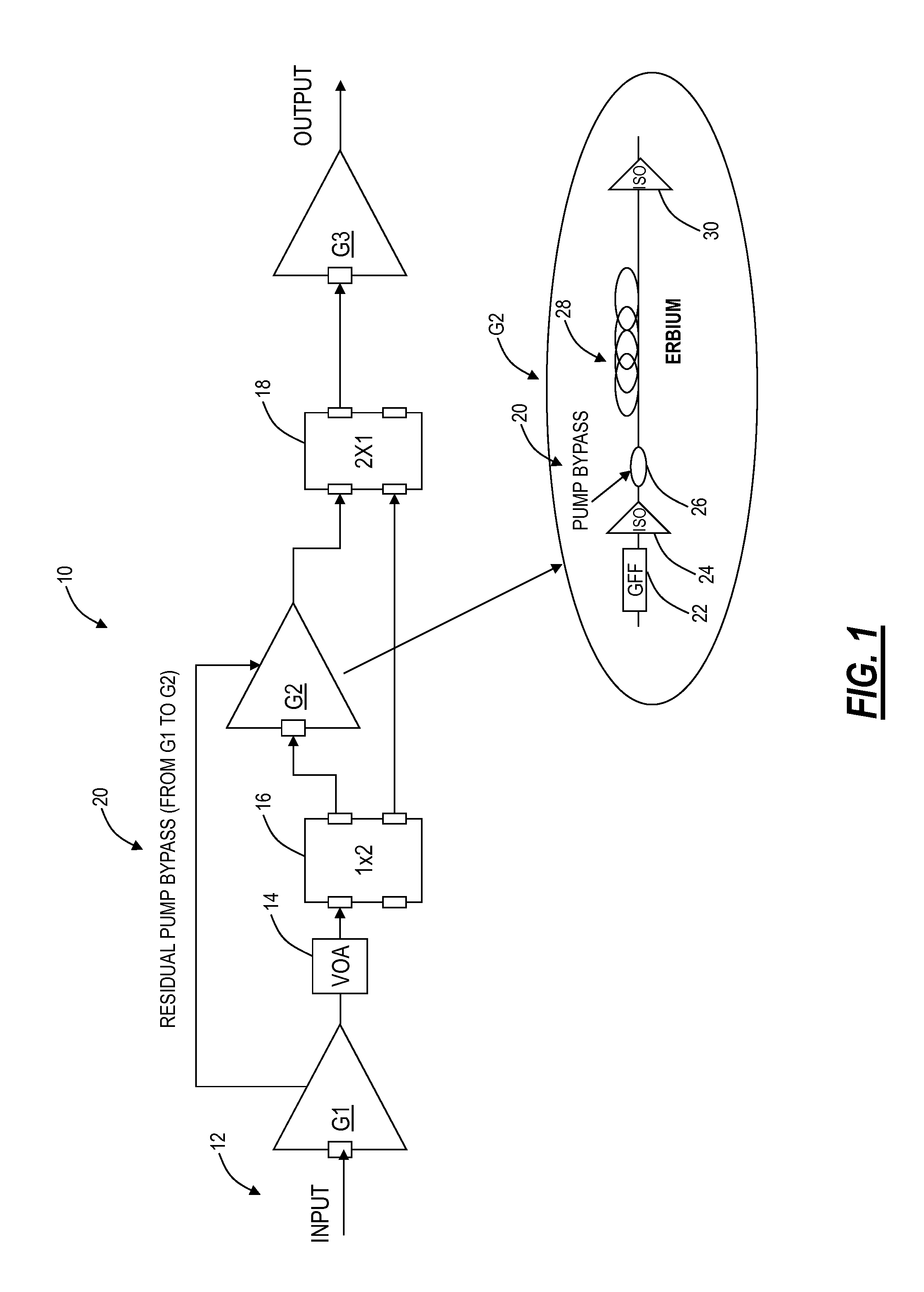
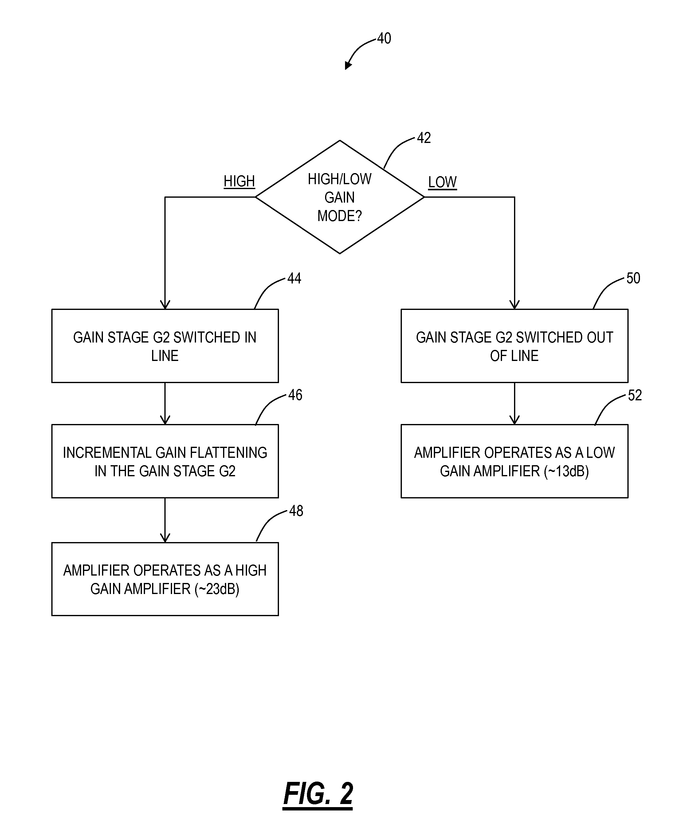
[0016]In various exemplary embodiments, an extended dynamic range optical amplifier such as an Erbium Doped Fiber Amplifier (EDFAs) is disclosed. The extended dynamic range optical amplifier can be optimized for high or low span loss conditions by switching an internal stage in or out of an internal light path within the amplifier. Advantageously, equipment manufacturers, network operators, etc. can deploy a single module despite having variability in span losses in actual networks. The extended dynamic range optical amplifier can include a low gain mode and a high gain mode with an internal switch to switch out a gain mid-stage in a low gain mode to extend the useful dynamic range of the amplifier. Further, the extended dynamic range optical amplifier can use residual pump power from an initial stage to pump the gain mid-stage in the high gain mode. For example, in the high gain mode, input power to the first stage is low for the pumps. Advantageously, this eliminates the need for ...


PUM


Abstract

An extended dynamic range optical amplifier, a method of operation, and a line amplifier configuration include an optical amplifier that can be optimized for high or low span loss conditions by switching an internal stage in or out of an internal light path within the amplifier. The extended dynamic range optical amplifier can include a low gain mode and a high gain mode with an internal switch to switch out a gain mid-stage in a low gain mode to extend the useful dynamic range of the amplifier. Further, the extended dynamic range optical amplifier can use residual pump power from an initial stage to pump the gain mid-stage in the high gain mode. Additionally, the extended dynamic range optical amplifier includes remapping of gain in the initial stage and the gain mid-stage to optimize the amplifier noise performance based on the maximum output power of the amplifier.

Description

FIELD OF THE DISCLOSURE[0001]The present disclosure relates generally to fiber optic systems and methods. More particularly, the present disclosure relates to extended dynamic range optical amplifiers such as Erbium Doped Fiber Amplifiers (EDFAs).BACKGROUND OF THE DISCLOSURE[0002]Optical amplifiers that amplify optical signals, i.e. wavelength division multiplexing signals (WDM), etc., without the need to convert the optical signals to an electrical signal. EDFAs include optical fiber doped with erbium along with associated pump lasers. Distributed Raman amplifiers utilize in-line optical fiber with associated pump lasers. Existing EDFAs use a mid-stage variable optical attenuator (VOA) to achieve variable gain operation. The variable gain operation allows the EDFAs to operate with a flat gain response over the entire bandwidth over a range of gain settings. However, the useful dynamic range, where the noise figure (NF) of the amplifier does not increase significantly with the reduc...

Claims


Application Information

Patent Timeline
Patent Type & Authority Applications(United States)
IPC IPC(8): H01S3/10
CPCH04B10/2916H04B10/293H01S3/06758H01S3/094084H01S3/1608H04B2210/003H01S3/0078H04B10/291H01S3/1003H01S2301/02H01S3/0064
Inventor SRIDHAR, BALAKRISHNANBAO, JUN
Owner CIENA
Why Eureka
Try Eureka