Variable damping force damper

a damper and variable technology, applied in the direction of shock absorbers, mechanical equipment, transportation and packaging, etc., can solve the problems of reducing the mechanical strength of the piston main body, affecting the smoothness of the telescopic, so as to reduce the number of assembly steps, prevent the deformation of the electric coil, and reduce the number of components

Active Publication Date: 2014-07-03
HONDA MOTOR CO LTD
View PDF5 Cites 11 Cited by
  • Summary
  • Abstract
  • Description
  • Claims
  • Application Information

AI Technical Summary

Benefits of technology

[0015]According to the present invention, since the outer yoke and the inner yoke are connected with each other by the metallic connection means, the electromagnetic coil is prevented from deforming easily even when the piston is strongly pressed against the inner wall surface of the cylinder. Thus, displacement between the axis of the cylinder and the axis of the piston is restrained, wear of the seal is suppressed, and wire break or the like in the electromagnetic coil becomes less likely to occur. In the structure in which the piston is provided with a pair of communication oil passages, one having an opening in one axial end and the other having an opening in an opposite axial end, and the valve plate is provided to each of the openings of the pair of communication oil passages, damping forces on the expansion side and the contraction side can be variably controlled by a single electromagnetic coil. In the structure in which the electromagnetic coil is offset toward one of the valve plates relative to an axially middle position between the valve plates, it is possible, for example, to make the damping force on the expansion side larger than the damping force on the contraction side. In the structure in which the connection means consists of a connection member made of a ferromagnetic material integrally with the inner yoke and the outer yoke, the number of components and the number of assembly steps can be reduced. In the structure in which the connection member is configured to have an axial size smaller than a thickness of the valve plate, the magnetic flux flowing through the connection member is reduced, and thus, a relatively large magnetic force can be obtained on each side of the electromagnetic coil. In the structure in which the connection means consists of a connection member made of a non-magnetic material, magnetic flux does not flow through the connection member, and thus, it is possible to increase the axial size of the connection member, thereby restraining relative displacement between the inner yoke and the outer yoke more effectively. Further, in the structure in which the connection means is disposed at a position spaced from the piston ring in an axial direction, bending, rotation and twisting of the piston can be suppressed effectively.
[0016]In the following, detailed description will be made of an exemplary embodiment, in which the present invention is applied to a mono-tube variable damping force damper constituting a front suspension of an automobile, with reference to the drawings. It is to be noted that with regard to the members and positional relationships in the exemplary embodiment, description will be made on the assumption that the upward direction in FIG. 2 indicates the “upward” direction.
[0017]As shown in FIG. 1, a front suspension 1 in the exemplary embodiment is of a so-called McPherson strut type, and includes, as main components thereof, a steering knuckle 3 (wheel-side member) rotatably supporting a wheel 2, a strut damper (hereinafter, simply referred to as a damper) 5 having upper and lower ends connected with a damper mount 4 (vehicle body-side member) and the steering knuckle 3, respectively, a lower ar

Problems solved by technology

In the variable damping force dampers disclosed in Patent Documents 1 and 2, since the electromagnetic coil is disposed between the inner yoke and the outer yoke, the mechanical strength of the piston main body is reduced, and this may cause the following problems.
This may cause deformation of the electromagnetic coil, such that the axis of the outer yoke is offset

Method used


Image

  • Variable damping force damper
  • Variable damping force damper
  • Variable damping force damper

Examples


first modified embodiment

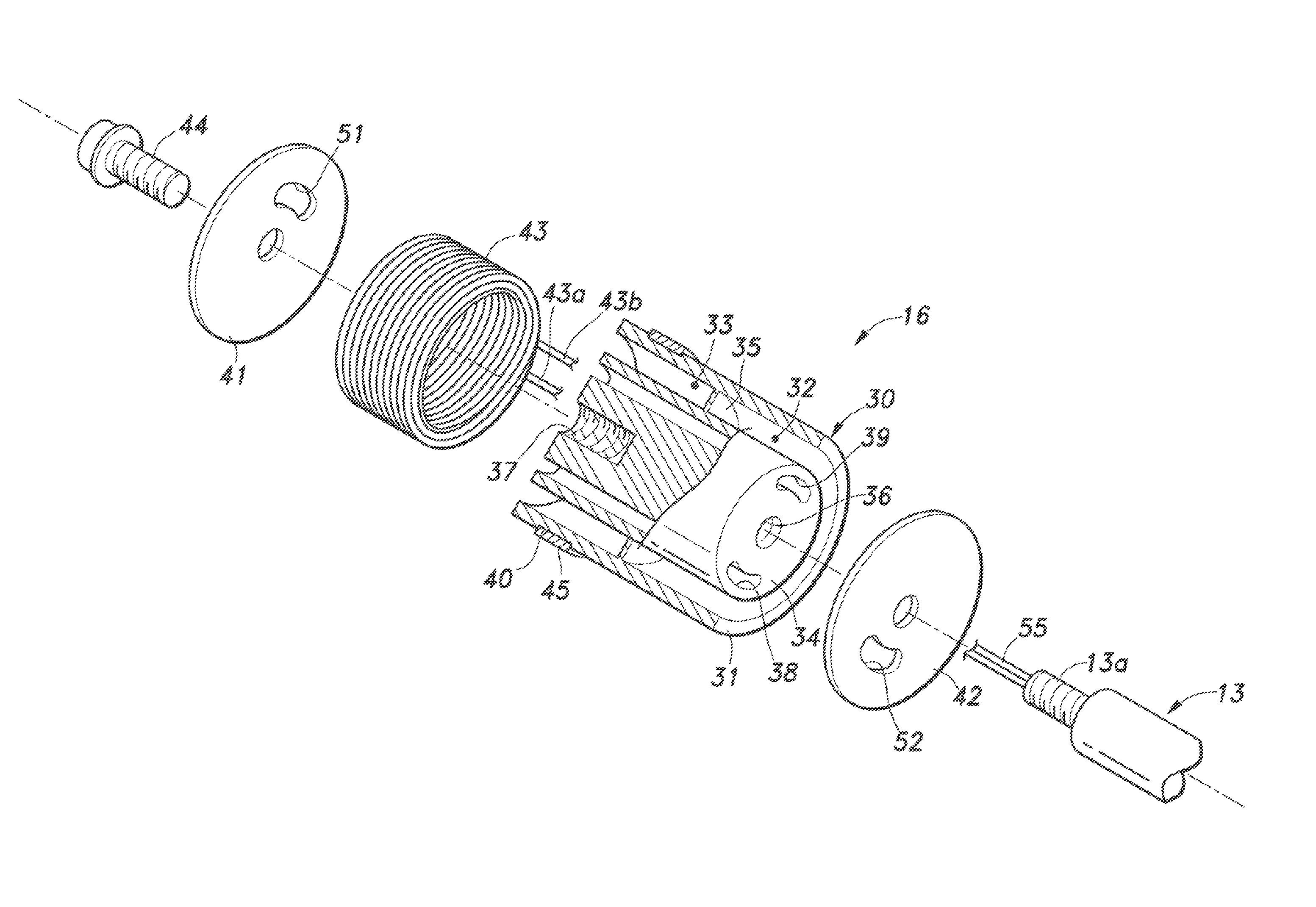
[0027]As shown in FIG. 6, in the piston 16 according to the first modified embodiment, the hollow cylindrical outer yoke 31 and the columnar inner yoke 34 are separately formed of a ferromagnetic material, and these yokes 31 and 34 are connected with each other by a hollow cylindrical connection member 61 made of a non-magnetic material (such as austenitic stainless steel or aluminum alloy). The connection member 61 is inserted between the outer yoke 31 and the inner yoke 34 and is secured to these yokes 31 and 34 by means of press-fitting, welding, adhesion or the like. In the first modified embodiment, a connection member made of a ferromagnetic material as shown in the exemplary embodiment is not included, and thus, the magnetic flux generated by the electromagnetic coil 43 acts upon the valve plates 41, 42 without leaking out in the middle, as shown by broken lines in FIG. 6. Further, the connection member 61 has a much larger axial size than the connection member in the exempla...

second modified embodiment

[0028]As shown in FIG. 7, in the piston 16 according to the second modified embodiment, the outer yoke 31 and the inner yoke 34 are connected with each other by the connection member 35 as in the exemplary embodiment, but the connection member 61 made of a non-magnetic material is securely fitted in a part of the first gap 32 on the side of the contraction-side valve plate 42. The mode of operation in the second modified embodiment is substantially the same as that in the foregoing exemplary embodiment, but owing to the combination of the connection member 35 and the connection member 61, relative displacement between the outer yoke 31 and the inner yoke 34 can be restrained more effectively.

third modified embodiment

[0029]As shown in FIG. 8, in the piston 16 according to the third modified embodiment, the outer yoke 31 and the inner yoke 34 are connected with each other by the connection member 35 as in the exemplary embodiment, but connection members 61, 62 each made of a non-magnetic material are securely fitted in a part of the first gap 32 close to the compression-side valve plate 42 and a part of the second gap 33 close to the expansion-side valve plate 41, respectively. The mode of operation in the third modified embodiment is substantially the same as that in the second modified embodiment, but relative displacement between the outer yoke 31 and the inner yoke 34 can be restrained even more effectively.


PUM


Abstract

Provided is a solenoid-type variable damping force damper that improves the strength of the piston and prevents wire break in the electromagnetic coil. A piston includes a piston main body, an expansion-side valve plate, a contraction-side valve plate, an electromagnetic coil, and a bolt. The piston main body is an integrally formed component made of a ferromagnetic material, and includes a hollow cylindrical outer yoke that is in slidable contact with an inner peripheral surface of a cylinder, a columnar inner yoke having an outer peripheral surface opposing an inner peripheral surface of the outer yoke via first and second gaps, and a connection member connecting the outer yoke and the inner yoke with each other at an axially middle position of the piston and separating the first and second gaps from each other. The electromagnetic coil is fitted in the second gap of the piston main body.

Description

TECHNICAL FIELD[0001]The present invention relates to a solenoid-type variable damping force damper for use in a suspension of an automobile, and particularly relates to technology for improving the strength of a piston and preventing wire break in an electromagnetic coil.BACKGROUND OF THE INVENTION[0002]A suspension is an important element that significantly affects the driving stability of an automobile, and typically includes, as main components thereof, a link (such as an arm, rod, etc.) that supports a wheel to be movable vertically relative to a vehicle body, a spring that is flexible to absorb impact from a road surface or the like, and a damper for damping the oscillation of the spring. Such a damper for an automotive suspension is typically embodied as a tubular damper which includes a hollow cylinder filled with hydraulic oil, a piston configured to slide in the cylinder in an axial direction, and a piston rod having an end connected with the piston, where the hydraulic oi...

Claims


Application Information

Patent Timeline
IPC IPC(8): F16F9/348F16F9/22
CPCF16F9/22F16F9/3484B60G17/08F16F9/535
Inventor NAKAJIMA, KIYOSHI
Owner HONDA MOTOR CO LTD
Why Eureka
Try Eureka