Process for Performing Automated Mineralogy

a mineralogy and automatic technology, applied in the field of automatic mineralogy, can solve the problems of difficult automatic mineralogy applications, difficult to distinguish hematite and magnetite, and difficult to accumulate x-ray spectrum

Active Publication Date: 2014-07-03
FEI CO
View PDF10 Cites 28 Cited by
  • Summary
  • Abstract
  • Description
  • Claims
  • Application Information

AI Technical Summary

Benefits of technology

[0008]An object of the invention is to provide an improved method and apparatus for identifying unknown compounds in a sample material. Embodiments of the present invention are directed to a method for determining the mineral content of a sample using an electron microscope. The method includes directing an electron beam toward an area of interest of a sample, the area of interest comprising an unknown composition of minerals. The working distance between the backscattered electron detector of the microscope and the area of interest of the sample is determined. Compensation is made for the difference between the working distance and a predetermined working distance in which the predetermined working distance being the working distance that provides desired grayscale values for detected backscattered electrons. One way of compensating for working distance variation is to used an autofocus feature of the microscope to adjust the working distance. Backscattered electrons from the area of interest of the sample are then detected.

Problems solved by technology

It takes considerable time to accumulate an x-ray spectrum.
Although magnetite and hematite can be easily distinguished qualitatively using optical microscopy, quantitative characterization by automated scanning electron microscopy / energy dispersive x-ray spectroscopy (SEM-EDS), such as MLA, is challenging because hematite and magnetite are similar in their chemical composition and BSE brightness.
This similarity makes differentiating hematite and magnetite difficult for automated mineralogy applications.

Method used


Image

  • Process for Performing Automated Mineralogy
  • Process for Performing Automated Mineralogy
  • Process for Performing Automated Mineralogy

Examples


Embodiment Construction

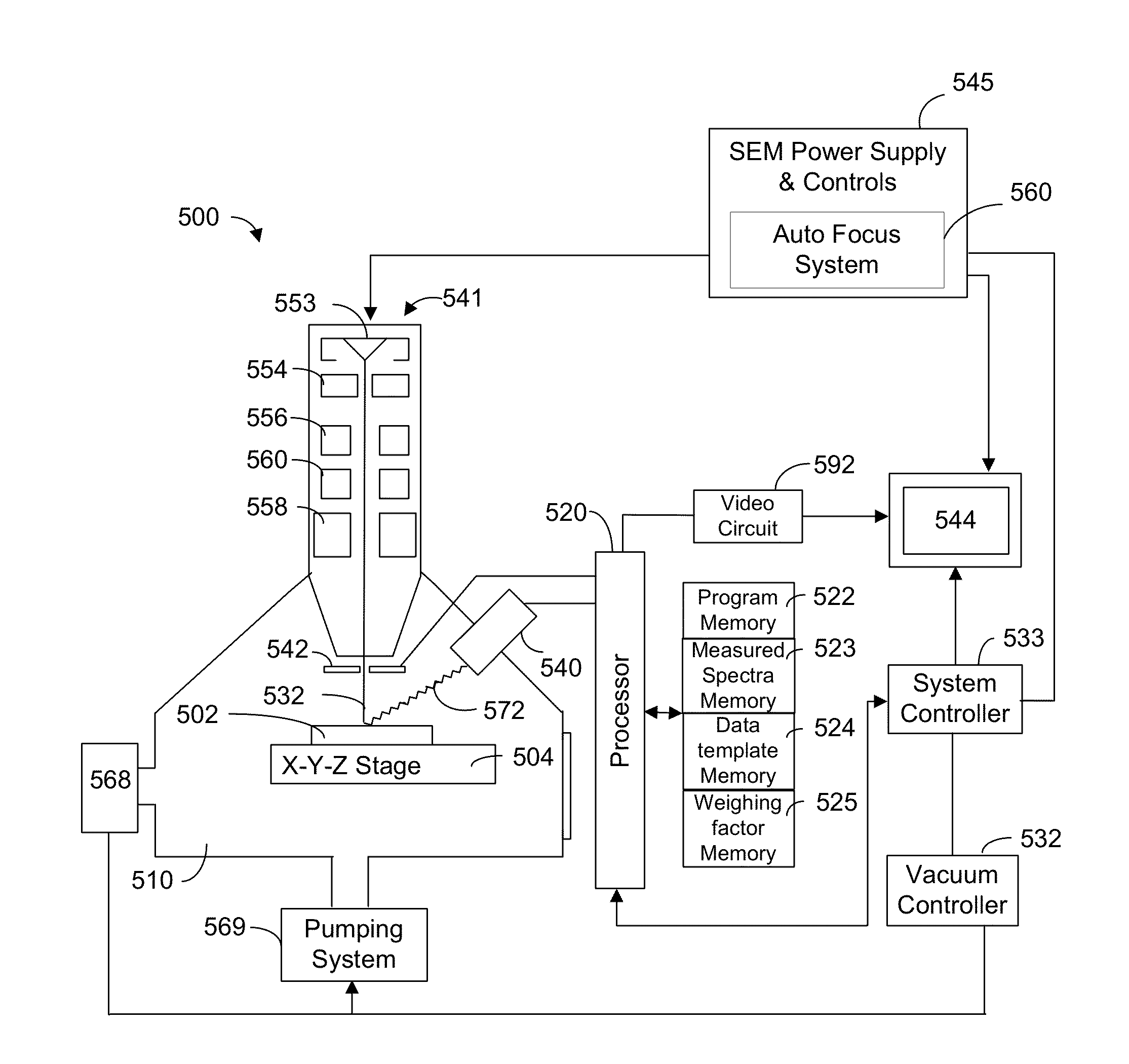
[0021]Embodiments of the present invention include a method for automatically configuring a scanning electron microscope (SEM)

[0022]In the MLA approach, mineral phases are first distinguished by their BSE grayscale levels during an on-line segmentation operation and then by their energy dispersive x-ray (EDX) spectrum. Minerals associated with a similar BSE values are segmented into a single phase. The results of a BSE mineral analysis determines the mineral phases and boundaries in a sample. This method of image segmentation allows BSE detectors to outline the regions of varying compounds in a sample which provides an easy means of separating the compounds and determining the overall content of a sample.

[0023]FIG. 8 shows a segmented BSE histogram reflecting standard BSE calibration. Standard BSE calibration is set to that the mounting media (resin) is kept at backscatter brightness values below 15, and gold at value of 250. This setting covers the BSE range of all common minerals....


PUM

PropertyMeasurementUnit
electron microscopeaaaaaaaaaa
compositionaaaaaaaaaa
distanceaaaaaaaaaa

Abstract

A method and system for determining the mineral content of a sample using an electron microscope. The method includes directing an electron beam toward an area of interest of a sample, the area of interest comprising an unknown composition of minerals. The working distance between the backscattered electron detector of the microscope and the area of interest of the sample is determined. Compensation is made for the difference between the working distance and a predetermined working distance in which the predetermined working distance being the working distance that provides desired grayscale values for detected backscattered electrons. One way of compensating for working distance variation is to used an autofocus feature of the microscope to adjust the working distance. Backscattered electrons from the area of interest of the sample are then detected.

Description

TECHNICAL FIELD OF THE INVENTION[0001]The present invention relates to the field of automated mineralogy, and in particular to the use of charged particle beams in automated mineralogy systems.BACKGROUND OF THE INVENTION[0002]Mineral analysis systems, such as the QEMSCAN and MLA available from FEI Company, Hillsboro, Oreg., have been used for many years to analyze mineral samples. To determine the type and relative quantity of minerals present in a mine, a sample in the form of small granules, is fixed in epoxy and placed in a vacuum chamber. An electron beam is directed toward a sample and, in a process called “energy dispersive x-ray spectroscopy” or “EDS,” the energies of x-rays coming from the sample in response to the electron beam are measured and plotted in a histogram to form a spectrum. The measured spectrum can be compared to the known spectra of various elements to determine which elements and minerals are present, and in what proportion. FIG. 1 shows a typical sample 100...

Claims


Application Information

Patent Timeline
Patent Type & Authority Applications(United States)
IPC IPC(8): G01N23/225
CPCG01N23/2252G01N23/203G01N23/2251G01N2223/072G01N2223/076G01N2223/079G01N2223/305G01N2223/32G01N2223/418G01N2223/616H01J37/21H01J37/20
Inventor SMITH, MICHAEL D.MOELLER, KURT
Owner FEI CO
Why Eureka
Try Eureka