Power storage device control system, power storage system, and electrical appliance

ontrol system technology, applied in the direction of charging/discharging current/voltage regulation, secondary cell servicing/maintenance, cell components, etc., can solve the problems of resistance increase and conventional power storage device capacity decrease, and achieve the effect of reducing the capacity of a power storage device due to charge, low power, and improving reliability of a power storage devi

Active Publication Date: 2014-07-03
SEMICON ENERGY LAB CO LTD
View PDF0 Cites 69 Cited by
  • Summary
  • Abstract
  • Description
  • Claims
  • Application Information

AI Technical Summary

Benefits of technology

[0011]An object of one embodiment of the present invention is to reduce deterioration of a power storage device or the like.
[0027]The reduction in the capacity of a power storage device due to charge can be decreased. The control of a power storage device can be performed with low power. The reliability of a power storage device can be improved. The safety of a power storage device can be improved. A novel power storage device can be provided. An efficient power storage device can be provided. The efficiency of charging a plurality of power storage devices can be increased.

Problems solved by technology

The conventional power storage device has problems of a capacity decrease and a resistance increase due to gradual deterioration by repetitive charge and discharge.

Method used


Image

  • Power storage device control system, power storage system, and electrical appliance
  • Power storage device control system, power storage system, and electrical appliance
  • Power storage device control system, power storage system, and electrical appliance

Examples


embodiment 1

Power Storage System

[0071]Examples of a power storage device and a power storage system will be described.

[1.1. Configuration]

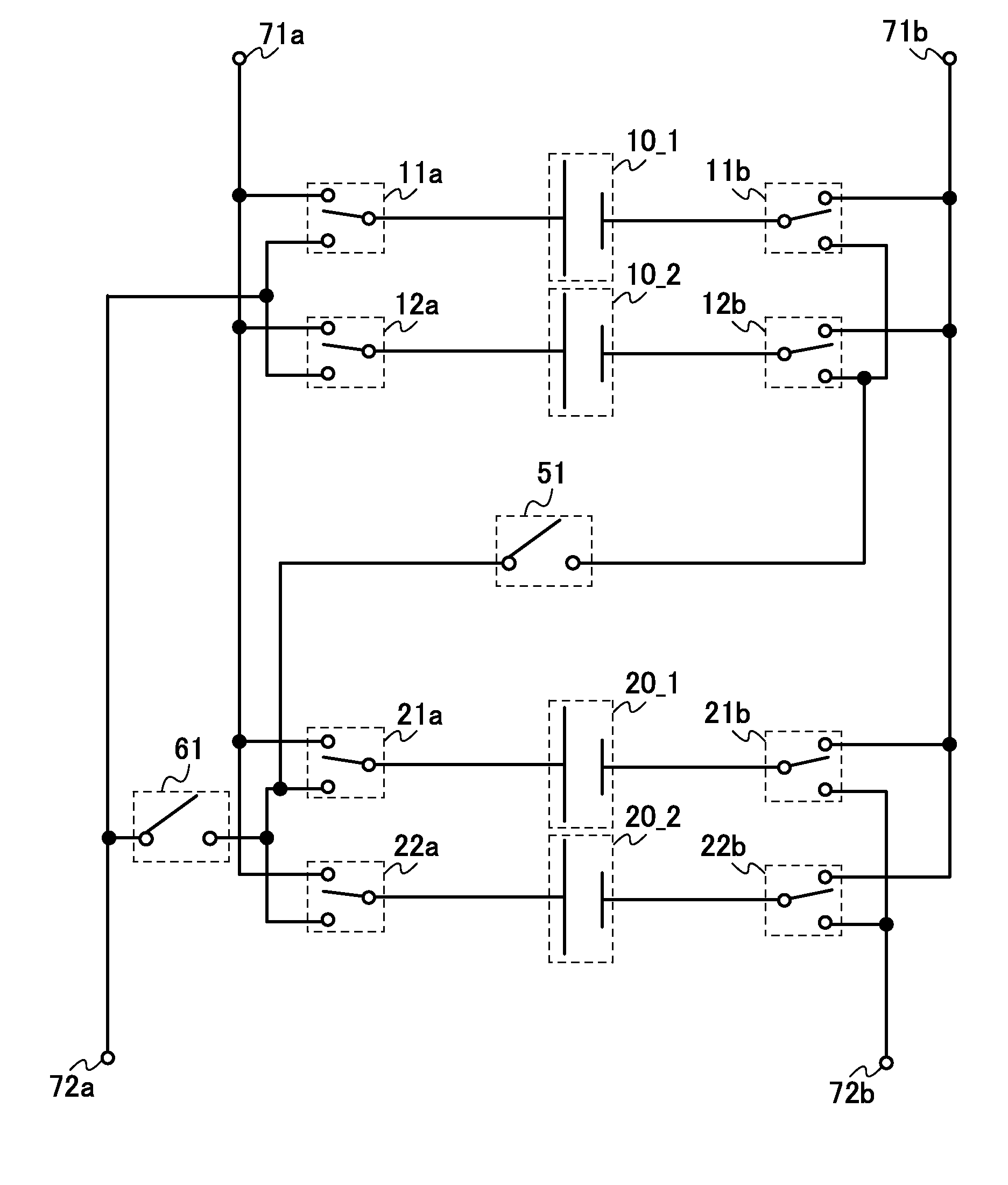
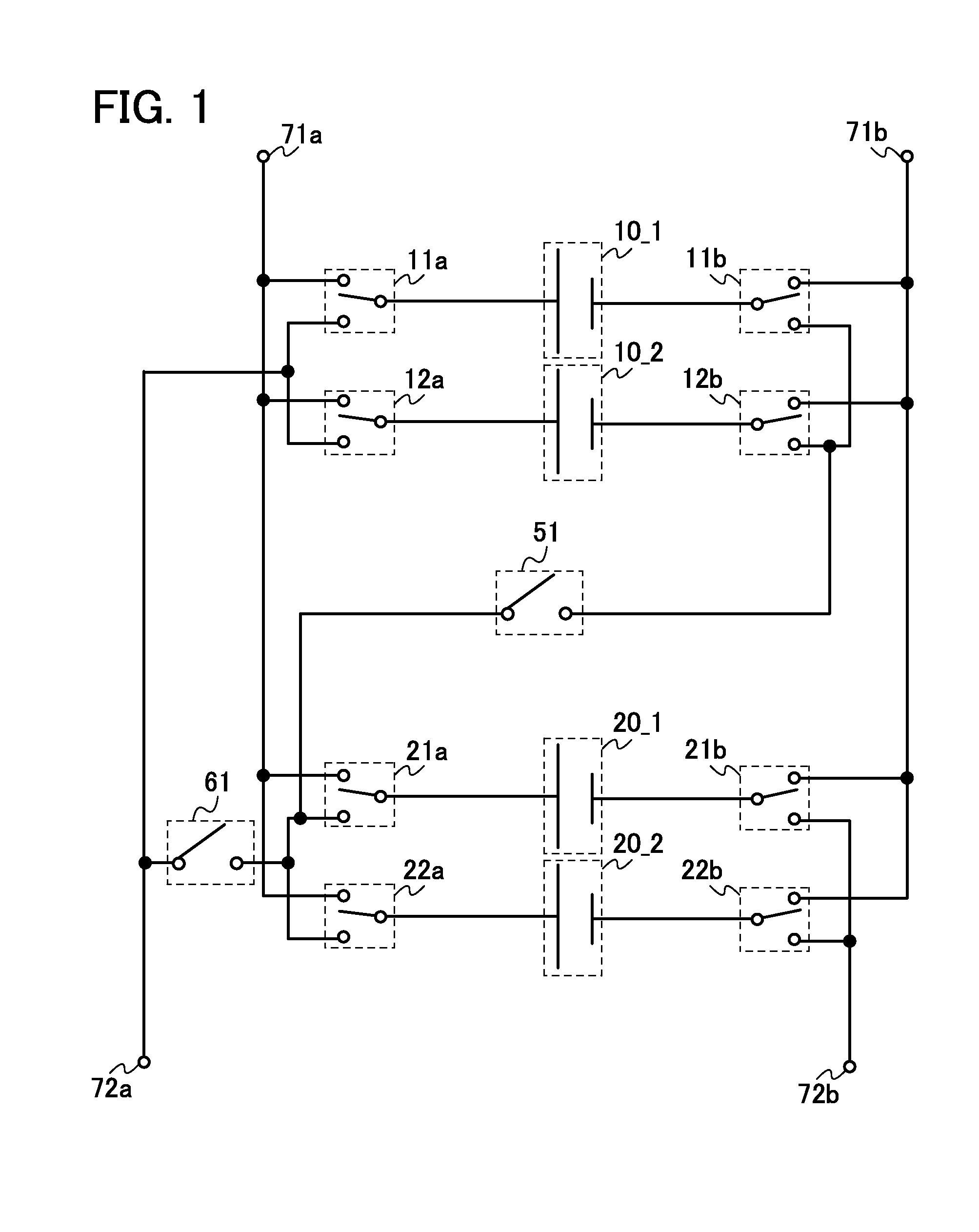
[0072]A circuit configuration example of a power storage system will be described with reference to FIG. 1.

[0073]The power storage system illustrated in FIG. 1 includes a power storage element 10_1, a power storage element 10_2, a power storage element 20_1, a power storage element 20_2, a pair of switches 11 (a switch 11a and a switch 11b), a pair of switches 12 (a switch 12a and a switch 12b), a pair of switches 21 (a switch 21a and a switch 21b), a pair of switches 22 (a switch 22a and a switch 22b), a switch 51, and a switch 61.

[0074]For example, the switch 11a and the switch 11b has a function of determining to which connection terminal the power storage element 10_1 is connected to, a pair of connection terminals 71 (a connection terminal 71a and a connection terminal 71b) or a connection terminal 72a. Alternatively, for example, the switch 11a has a fu...

embodiment 2

Power Storage Device Control System

[0137]An example of a control system of a power storage device that can be used in a power storage system of one embodiment of the present invention will be described. Note that the description of the power storage system with reference to FIG. 1 to FIG. 6 can be referred to for the same portion, as appropriate.

[2.1. Configuration]

[0138]An example of a control system of a power storage device will be described with reference to FIG. 7.

[0139]A circuit 200 shown in FIG. 7 includes a pair of switches 11 (a switch 11a and a switch 11b), a pair of switches 12 (a switch 12a and a switch 12b), a pair of switches 21 (a switch 21a and a switch 21b), a pair of switches 22 (a switch 22a and a switch 22b), a switch 51, a switch 61, an encoder 240, a current detection circuit 245, a semiconductor circuit 246, a pair of connection terminals 201 (a connection terminal 201a and a connection terminal 201b), a pair of connection terminals 202 (a connection terminal ...

embodiment 3

Register

[0223]Further, an example of a structure of the register which can be used in each circuit block of the semiconductor circuit 246 will be described with reference to FIGS. 10A and 10B.

[3.1. Configuration]

[0224]The register illustrated in FIG. 10A includes a memory circuit 651, a memory circuit 652, and a selector 653.

[0225]The memory circuit 651 is supplied with a reset signal RST, a clock signal CLK, and a data signal D. The memory circuit 651 has a function of storing data of the data signal D in accordance with the clock signal CLK and outputting the data as a data signal Q. For example, a register such as a buffer register or a general-purpose register can be used as the memory circuit 651. As the memory circuit 651, a cache memory including a static random access memory (SRAM) or the like can be provided. Data of such a register or a cache memory can be stored in the memory circuit 652.

[0226]The memory circuit 652 is supplied with a write control signal WE, a read contr...


PUM

PropertyMeasurementUnit
off-state currentaaaaaaaaaa
frequencyaaaaaaaaaa

Abstract

Deterioration of a power storage device is reduced. Switches that control the connections of a plurality of power storage devices separately are provided. The switches are controlled with a plurality of control signals, so as to switch between charge and discharge of each of the power storage devices or between serial connection and parallel connection of the plurality of power storage devices. Further, a semiconductor circuit having a function of carrying out arithmetic is provided for the power storage devices, so that a control system of the power storage devices or a power storage system is constructed.

Description

BACKGROUND OF THE INVENTION[0001]1. Field of the Invention[0002]The present invention relates to an object (a product including a machine, a manufacture, and a composition of matter) and a method (a process including a simple method and a production method). In particular, the present invention relates to a power storage device, a control system of a power storage device, a power storage system, an electronic circuit, a semiconductor device, a display device, a light-emitting device, and an electrical appliance, and further to a driving method thereof and a manufacturing method thereof. More specifically, the present invention relates to a power storage device, a control system of a power storage device, a power storage system, an electronic circuit, a semiconductor device, a display device, a light-emitting device, and an electrical appliance which include an oxide semiconductor, and further to a driving method thereof and a manufacturing method thereof.[0003]2. Description of the ...

Claims


Application Information

Patent Timeline
Patent Type & Authority Applications(United States)
IPC IPC(8): H01G11/06H01M10/44H01M10/42H02J7/00H02J7/02
CPCH01G11/06H02J7/007H01M10/441H01M10/425H02J7/0013Y02B40/00H01M10/4207H02J7/0069Y02E60/10Y02T10/70H02J7/0024H01G11/10H01M4/5825H01M10/0525
Inventor TAKAHASHI, MINORUMOMO, JUNPEISHIONOIRI, YUTAKA
Owner SEMICON ENERGY LAB CO LTD
Why Eureka
Try Eureka